Wind Design For Roofing: Misconceptions and consequences
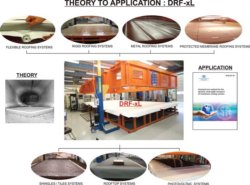
However, this is all about to change. Over the past decade and a half, a group called the Special Interest Group for the Dynamic Evaluation of Roof Systems (SIGDERS) (Visit sigders.ca). has been working toward the goal of having a unified standard and calculation tool for use with NBC. The new Canadian Standard Association (CSA) A123.21-10, Standard Test Method for the Dynamic Wind Uplift Resistance of Membrane-roofing Systems, has been developed to assist designers in designing and selecting the right assembly to withstand wind forces. The interesting part of this standard is it breaks away from the normal thinking of testing.
Available design standards
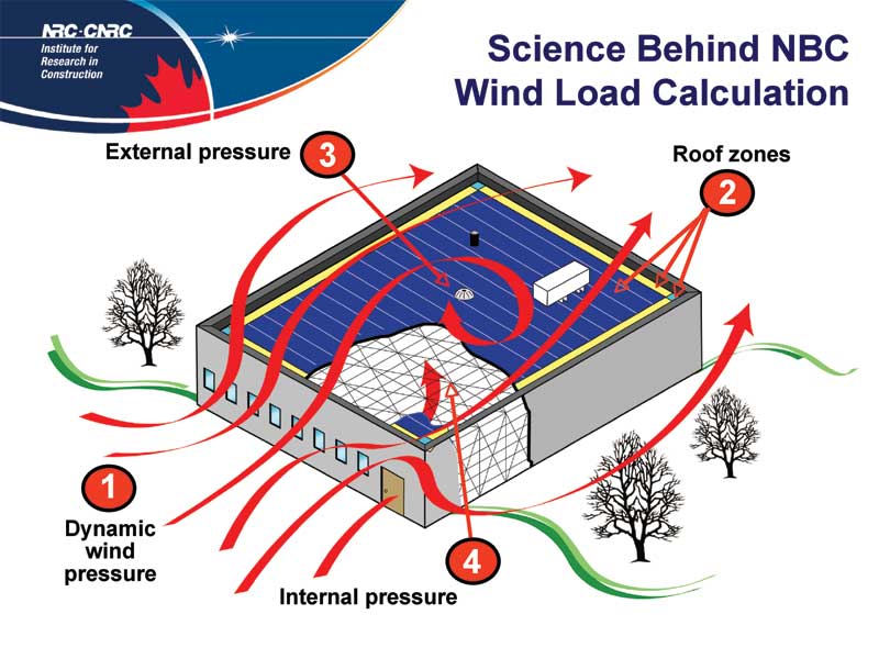
Both the FM Global and Underwriters Laboratory (UL) standards are for static wind uplift design; this means the roof is pressurized to a specific pressure and held for one minute. Once the minute is up, if the membrane has not failed, it is deemed to have passed that pressure category. Of course, no wind storm has a nice, constant wind speed that never changes direction. The CSA standards actually take into account the frequency of gusts and varying intensity, and more accurately replicates the actual wind effects to which the building will be exposed. It also allows use of the calculation from NBC Part 4 to accurately calculate wind speed.
Roof assemblies conforming to CSA A123.21 must be tested to determine the roof assembly’s wind uplift performance. Currently, Exp Global is the only certified testing laboratory; it tests roof assemblies from manufacturers and provides reports on its website outlining:
- wind pressures to which the roof is tested;
- design wind pressures (with safety factor); and
- acceptable components within the assembly, including insulation and vapour barrier types and thicknesses. (For more information, visit www.exp.com/en/rooftesting).
CSA A123.21 is rumoured to be implemented in the current code cycle which should be out this year or the following one in 2015. This would include mechanically attached roof membrane systems, as well as adhesively attached roof systems. This will finally provide a single source guide for the design and selection of roof assemblies that also is derived from NBC requirements.
Images courtesy NRC
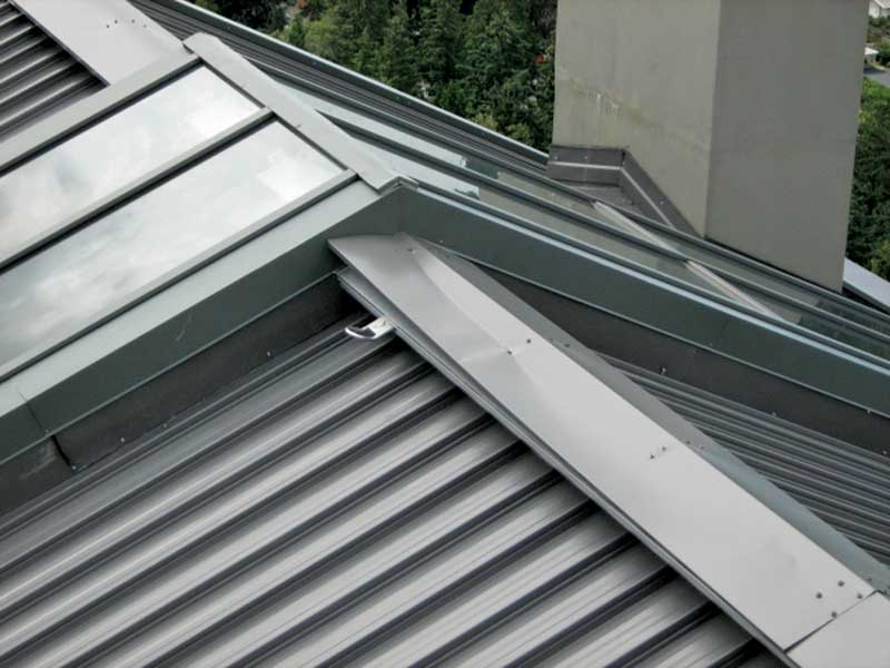
Perimeter edge flashings
The designer knows how many fasteners to use, and that the corners and perimeters need more than the rest of the roof. He or she has a well-designed roof assembly, but should remember the majority of catastrophic roof failures start at the perimeter flashings. There currently is no standard for perimeter flashings that can be used to design based on the existing NBC, not to mention there is no calculation within the code for determining the wind forces exerted on the flashings.
Within the industry, many of the roof flashings installed have an inseam clip every 3 m (10 ft) and, at best, mechanical fasteners on the interior surface of the flashing. However, the majority of the wind pressure is applied to the exterior face of the metal and results in it prying off. Typically, exposed fasteners are not installed on the exterior face from an appearance or architectural viewpoint. As this face is usually visible, a cleat or clip installed in the drip edge is appropriate, but rarely done.
A properly designed cap flashing will almost always have a continuous cleat or clip installed in the drip edge of the external face of the metal or exposed fasteners. When a cleat or clip is installed in the drip of a flashing, it is usually 100 to 150 mm (4 to 6 in.). At this length, the cleat does not have enough strength to adequately resist wind forces.
Another area where cleat design or installation is overlooked is the gauge of the metal. Typically, the cleat needs to be one gauge heavier than the cap flashing, but this will vary depending on the forces, the type of metal used, and the configuration of the drip edge/hem. When exposed fasteners are used, the frequency of the fasteners is quite high, typically 450 mm (18 in.) on centre (oc) or higher, again, depending on the variables. However, adequate frequency of exposed fasteners is rarely achieved.
Flashing standards
There are very few standards or guidelines designers can use to assist with the design of perimeter cap flashings. The standard most people refer to is American National Standards Institute (ANSI)/Single-ply Roofing Institute (SPRI) standard ES-1, Wind Design Standard for Edge Systems Used with Low-slope Roofing Systems. (For more, visit www.spri.org). This provides guidelines on how to calculate pressures on various types of flashings and that the flashing must be tested to meet the design. As with the UL and FM Global standards, it is a static test and does not closely represent the true affect of wind on a building.
ANSI/SPRI ES-1 is not directly referenced by NBC. Nevertheless, Appendix A, “Explanatory Material,” A5.6.2.1, “Sealing and Drainage,” references two guides for flashing design to prevent moisture entry. These guides––Sheet Metal and Air-Conditioning Contractors National Association’s (SMACNA’s) Architectural Sheet Metal Manual and the National Roofing Contractors Association’s (NRCA’s) Roofing and Waterproofing Manual––both use ANSI/SPRI ES-1 for their flashing design details. However, there is always a catch; in this case, the calculation on which the standard is based does not include Canadian weather data. As noted, one cannot take NBC data and use it to perform the calculations either.
Currently, the National Research Council of Canada (NRC) (Visit nrc-cnrc.gc.ca). is working with industry stakeholders and the University of Ottawa to develop a calculation tool and testing protocol for perimeter flashings. Still in its infancy, the project is the first attempt to accurately simulate the dynamic effects of wind on perimeter flashings, and will be based on NBC’s terminology and requirements. This standard will be another part of CSA A123.21; however, it will not be completed for several years. In the meantime, designers will have to use the resources available and rely on local knowledge or compare to similar areas within the country’s neighbours to the south to assist in perimeter flashing design.
Conclusion
Whenever a roof is going to be installed on a building, a designer must complete a wind uplift design for it. This must include perimeter flashings and accessories for the long-term success of the roof to be realized. Although there may be a lack of available resources, one must use the information available to ensure well-performing roofs are achieved.
Josh Jensen, AScT, CHI, RRO, RRC, is an associate and manager of the roofing division of JRS Engineering, a building envelope and roofing firm providing service in Western Canada and the northwestern United States. With almost a decade of roof consulting design and investigating experience, he received his education from the British Columbia Institute of Technology (BCIT). Jensen is actively involved in industry development, and currently serves on the standards technical panels for Underwriters’ Laboratories (UL) roof wind uplift resistance and roofing covering testing standards, and the National Research Council of Canada (NRC) panel for roof edge system technology. He can be reached via e-mail at josh@jrsengineering.com.
Sign up for our weekly newsletter
Construction Canada weekly newsletters give the latest AEC industry news for those who build, design, engineer, specify, renovate or operate in the built environment.
Products & Services


Read the Latest Issue