Wind design for modular vegetated roofing systems
Wind effects on modular vegetated systems
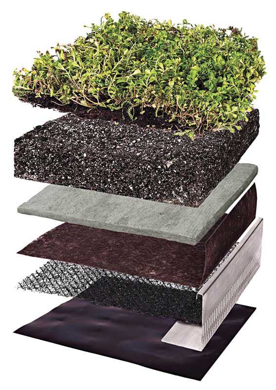
Vegetated modules contain mature vegetation that are pre-grown on mats or in trays and delivered at near complete vegetation coverage. Compared to traditional built-in-place systems, modular systems have the advantages of significantly shorter establishment time and lower maintenance needs. The mature roots bind the growing medium together, and the high vegetation coverage protects the medium from scouring. Research has also shown high vegetation density increases surface roughness and reduces wind forces experienced by the green roof. As a result, the German FLL Green Roof Guidelines recommend using pre-vegetated systems on high wind areas.
Wind tunnel studies showed the weight and design of the vegetated modules, such as trays and mats, govern their wind uplift behaviour. Wind suction creates uplift force on the vegetated modules. When the uplift force exceeds the module weight, it can become airborne and overturned.
The modules are permeable and have gaps at the joints, which allow air to enter and equalize the underside pressure and the surface pressure. Pressure equalization reduces the net uplift force on the module. The higher the pressure equalization, the higher wind force is needed to lift the module, the higher its wind resistance.
Interlocking mechanisms between the modular trays allow the uplift force to be shared among the modules, thus allowing the vegetated system to collectively resist higher wind forces. However, if one module does become airborne, the wind drag can lift adjacent modules as they are interlocked. This can create a domino effect where all the modules are overturned.
Vegetated mats also reduce the net wind uplift forces through pressure equalization. Their large size (1 x 2 m [39 x 78 ft] typical) allows the uplift force to be shared over a larger area, making them more difficult to lift. However, mat uplift can still occur if the wind is high enough (e.g. at the corner region of the roof) when the net uplift force is greater than the mat weight (See “Wind Flow Testing of Vegetated Mats”).
Vegetated modules come in a wide range of weight. They also vary in material and design, so the degree of pressure equalization differs considerably from one assembly to another. Therefore, it is necessary to test and determine the wind resistance. This can be done using the CSA A123.24 standard test method.
CSA A123.24-15
CSA A123.24-15 determines the wind resistance of modular vegetated roof assembly (MVRA), consisting of a roofing system (RS) and a vegetated system (VS), when subjected to dynamic wind flow and loading cycles. It is applicable to modular vegetated systems that are pre-grown offsite with a minimum of 80 per cent vegetation coverage.
Each MVRA is subjected to the following two tests to measure the roof assembly’s wind uplift resistance and wind flow resistance.
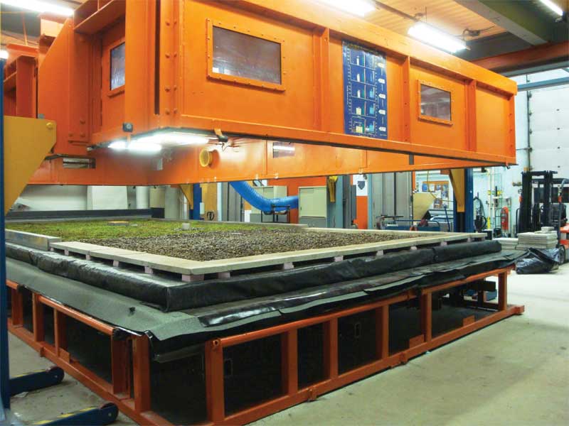
Wind uplift resistance
The MVRA is installed on the test table, instrumented with pressure and deflection sensors, and subjected to dynamic wind load cycles to simulate wind suction on the roof in accordance to CSA A123.21, Standard test method for the dynamic wind uplift resistance of membrane-roofing systems (Figure 4). The test is terminated when the specimen fails as defined in CSA A123.21 or when the net uplift deformation of the above-deck components exceeds 2L/240, where L is the deck structural span in feet.
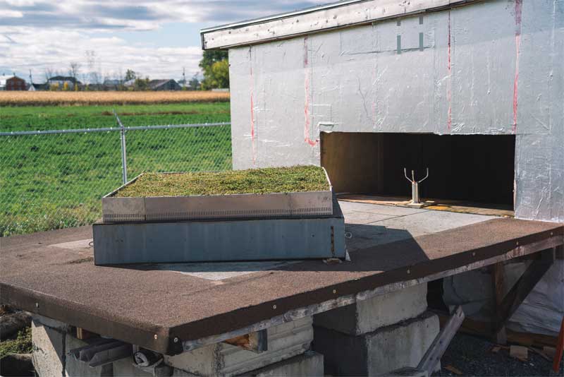
Wind flow resistance
The MVRA is installed on a test rig, which is placed in front of an airflow machine and yawed at 45 degrees to the airflow to simulate corner wind effects (Figure 5). The test starts with a wind speed and continuously moves up in increments of 10 km/h (6.2 mph) until failure occurs, as defined by overturning of any components within the test assembly or sliding or displacement of any components greater than 25 mm (1 in.).
Sign up for our weekly newsletter
Construction Canada weekly newsletters give the latest AEC industry news for those who build, design, engineer, specify, renovate or operate in the built environment.
Related Products & Services

Read the Latest Issue