Virtual air barrier and dynamic buffer zone for a heritage building envelope
The sensors included the thermocouples for temperature measurements and RH probes and pressure tap (tubes) with associated pressure transducers to determine air pressure differences. The sensors for these measurements were grouped into monitoring stations. There are six stations for the building. Five of them are located in the exterior walls of the building and one is on the roof to obtain local weather conditions. The sensors were wired to a direct digital control (DDC) building management system in the maintenance office of the building.
The data was collected on a continuing basis and stored in a data logger. The data was then tabulated as hourly results. The data collection started in late fall 2017 and continues to this day. For the purpose of this report, the data analysis was limited to December 2017 to end of January 2018.
VAB/DBZ performance analysis
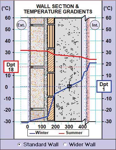
Figure 4 (page 43) illustrates the air pressure differences between the indoor and the wall cavity (red) and the pressure difference between the indoor and the outdoor (blue). The indoor was chosen as the reference pressure (atmospheric) for these difference measurements. Note the cavity pressure (red) is slightly positive or above the indoor pressure (reference) and nearly constant. Cavity air then leaks out of the wall cavity. It is this pressure difference that prevents indoor air from exfiltrating into or through the exterior wall cavities. The indoor to outdoor pressure difference is indicative of the pressure difference on the exterior wall from stack effect, wind, and mechanical ventilation.
The analysis above illustrates the effectiveness and efficiency of the VAB/DBZ of the Viterra Building in Regina. It is performing as expected. During an initial system operation review in December 2017, it was determined the supply air used for pressurization could be reduced without losing condensation control performance. The system was adjusted accordingly with a 17 per cent reduction in air supply. Analysis of the wall cavity moisture and pressure data revealed condensation control performance remained near perfect over the heating season of 2017 to 2018.
| AIR SEALING THE FAÇADE AND INDOOR FINISH |
|
Architecturally, the virtual air barrier/dynamic buffer zone (VAB/DBZ) system performance depends on the airtightness of the exterior wall (or roof surfaces) containing the cavity air. It is important to review the characteristics of the exterior walls or roof of the building to be restored to determine the type and extent of architectural intervention required to provide adequate air sealing of the exterior wall. There is a similar requirement for roofs albeit the waterproofing provides an adequate air seal on the outdoor side, but most often there exists a major discontinuity at the roof wall junction or parapets. The challenge for a roof VAB/DBZ is the construction of a continuous indoor side plane of airtightness encapsulating the roof cavity and a major intervention at the roof wall or parapet junction to compartment the roof cavity effectively. |
Recommendations
The VAB/DBZ technology is simple in concept but moderately difficult to design and construct. There is little or no literature to guide the professionals in this technology. Further, it does not fall cleanly into one professional camp or the other. Building teams wanting to pursue the design of a VAB/DBZ for a project may be guided by two main objectives.
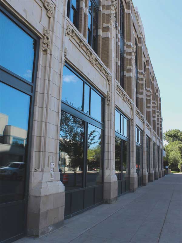
Photo © Roger Mitchell
The first objective is an architectural intervention providing the best cavity seal possible with the cladding system on the outdoor side, sealing the indoor side with the indoor finishes linked continuously from foundation to roof, and creating an airtight seal around the perimeter of the building assembly cavity. A continuous single cavity is not always required. If the building is a difficult form, the exterior walls may be separated into individual cavities. Perimeter conditions of a wall cavity include sealing at roof wall parapets, connections to adjoining buildings, header, jams, and sill of windows and doors, floors and partitions, and major penetrations from the indoor or outdoor side. It is unnecessary to seal the wall cavity perfectly. If the total leakage area from a wall cavity can be quantified after the architectural intervention, the design criteria would require a leakage area of no more than 3000 mm2 (4.65 si) to 4839 mm2 (7.5 si) per 0.1 m2 (1 sf) of exterior wall. There are numerous ways to determine the location and severity of exterior wall leakage characteristics and these include pressure testing with a smoke generator to locate leaks and test openings for a positive visual confirmation.
From the mechanical engineering point of view, the supply air fan capacity to create the wall cavity pressure required may be targeted between 12 L/s (25 cfm) and 19 L/s (40 cfm) per 9 m2 (100 sf) of exterior wall in masonry heritage buildings. Other types of exterior walls need to be assessed on an individual basis. If the pressure difference between the wall cavity and the indoor is close to zero, additional architectural intervention may be required to better seal the exterior wall cavity enclosure elements. If the pressure difference of the cavity to indoor side is higher than 10 Pa, the fan supply air to the exterior wall cavities must be reduced. Additionally, it is recommended the maximum fan head pressure not exceed 125 Pa although ducted distance and flow resistance may require a slight increase in head pressure as in the Viterra project. These rules of thumb have met the requirements of several VAB/DBZ projects undertaken in Canada including the Viterra building.
| OBSTRUCTIONS IN THE WALL CAVITY |
|
The virtual air barrier/dynamic buffer zone (VAB/DBZ) concept is designed to pressurize an exterior wall cavity. A clean, well-defined exterior wall cavity is not essential. Cavity pressure distributes quickly even in a rubble-filled masonry wall. Since pressure travels at the speed of sound, (approximately 330 m [1000 ft]/s), a pressure pulse is immediately distributed even in the most obstructed wall cavity of an exterior wall. This was clearly demonstrated at the Viterra building, Regina, Sask. It has an obstructed wall cavity with infill masonry. A test opening undertaken in the north wall indicated the immediate appearance of a pressure pulse on the other side of the building. The flow of air through the wall cavity was irrelevant. |
The VAB/DBZ technology is a collaboration of both architecture and engineering as are many elements of building design. However, it takes a knowledgeable multidisciplinary design team to recognize the need for, and potential effectiveness of such a system. This technology, the VAB/DBZ concept, and application is so forgiving for exterior walls and roof condensation control, that even with incomplete architectural intervention, an undersized pressurization and/or heating system, and imperfect construction sealing, it will function well, but may consume more heating energy.
 Rick Quirouette, B.Arch., is a senior building science specialist with almost four decades of experience in building science and technology. He is a life member of the Alberta Building Envelope Council (ABEC) and a past-president of the National Building Envelope Council (NBEC). Operating as Quirouette Building Specialists Ltd., he can be reached at rick.quirouette@gmail.com.
 Roger Mitchell, SAA (Ret.), FRAIC, is the principal architect in his eponymous firm Mitchell Architect. During his 43-year career, Mitchell has provided specialized consulting in building accessibility issues and sustainable design. He has extensive experience in effective management of planning, design, and production team. He can be reached at rmitchellarch@gmail.com.
 Robert J. (Bob) England, P.Eng., offers specialized building mechanical consulting services through his boutique-styled firm R. J. England Consulting. England has worked in the mechanical engineering field for most of his career in geographically varied building projects. He enjoys heritage building work, as each commission presents unique engineering challenges requiring innovative solutions. He can be reached at bob@rjengland.com.
Sign up for our weekly newsletter
Construction Canada weekly newsletters give the latest AEC industry news for those who build, design, engineer, specify, renovate or operate in the built environment.
Related Products & Services

Read the Latest Issue