Virtual air barrier and dynamic buffer zone for a heritage building envelope
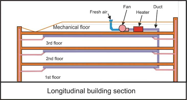
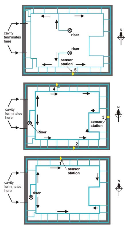
Figure 3 illustrates the DBZ duct layouts installed in the suspended ceiling of each floor of the building. The yellow diamond shows the location of the temperature, RH, and all the pressure sensor stations.
VAB/DBZ operation
The VAB/DBZ system is operated from mid-October to April-end for Regina’s climate conditions. It consists of starting the system pressurization fan and indirectly fired natural gas makeup air unit heater and letting the system operate according to a program protocol for the duration of the fall startup, winter, and spring periods to the shutdown event around April 15.
The VAB/DBZ mechanical system controls the outdoor air supply, heater conditions, and air temperature settings, amount of air to the risers for each floor, and VAV boxes. Additionally, the ducts connecting to the wall cavities were supplied with manual dampers for the initial balancing of the supply air and pressure difference measurements.
| VAB/DBZ SUPPLY AIR ON THE WARM OR COLD SIDE OF INSULATION |
| The virtual air barrier/dynamic buffer zone (VAB/DBZ) supply air can be pumped into a wall cavity on the warm side of an insulated exterior wall cavity or on the cold side. If a building envelope is composed of a brick or stone veneer with a drainage cavity, insulation, and vapour barrier, the VAB/DBZ supply air is directed into the wall cavity on the cold side of the insulation. In this case, the supply air need not be pre-heated but the ducts may require insulation if routed on the indoor side of the building to prevent condensation from dripping onto a suspended ceiling or a floor below. To augment the cavity air pressure in a pressure-equalized rainscreen wall, the drains and vents of the brick cladding and any other openings leading into the cavity of the exterior wall must be sealed. The exterior walls can still be drained with tubes if required. The tube drains do not represent a significant uncontrolled leakage area.
Alternately, if the VAB/DBZ supply air is pumped into a cavity on the warm side of the insulation, as it might occur with an insulated precast wall cladding, it is best to pre-heat the supply air to a level determined by a temperature gradient analysis. This maintains indoor finish surface temperature at ambient comfort conditions and the entire wall cavity dry (Figure 5). If an exterior wall is uninsulated, such as with most heritage buildings, and there is no clear cavity condition, then the supply air temperature may be set to halfway between the indoor and outdoor average monthly temperature. As the outdoor temperature varies dynamically, an average temperature difference for the coldest month is adequate to identify a fixed temperature setting for the wall cavity under consideration. For a more efficient heating system, a temperature control approach will save energy without affecting DBZ performance. Lastly, if the VAB/DBZ cavity is well sealed then there will be little heated air supplied. If the cavity is more porous than expected, the heating system will provide more heated air to the exterior wall cavity. |
The VAB/DBZ system is controlled by the pressure difference between the wall cavity of each floor and the interior pressure. The wall cavity pressure is determined by the amount of air pumped into the wall cavity. In Viterra, the DBZ supply air to each floor wall cavity is limited to a maximum flow of 810 L/s (1716 cfm) for the first floor, 575 L/s (1218 cfm) for the second, and 520 L/s (1101 cfm) for the third.
The wall cavity pressure is governed by the pressure difference induced by the DBZ supply air and the indoor pressure. To ensure cavity pressure does not rise too high, the wall cavity pressure difference with the indoor side is controlled between zero and 10 Pa (0.04 in. H2O). If the cavity to indoor pressure difference rises near the maximum pressure limit of 10 Pa, the VAV box for that floor limits the DBZ air supply to the cavity. If the wall cavity to indoor pressure difference operates near zero pressure variance, the DBZ supply air is increased to near maximum flow for that floor. In this way, the wall cavity pressure difference for each floor is controlled independently of the exterior wall cavity airtightness conditions. VAV boxes allow the DBZ system to respond independently to rises in barometric pressure, stack effect pressure, wind pressure, and the building ventilation pressures on each floor.
The condensation control for the wall cavity is the same whether operated at high or low pressure difference but the cost of heating the supply air (with a temperature of 10 C [50 F]) increases if the wall cavity is inadequately sealed. The performance of the system is quite forgiving, so much so the concept has been dubbed fail safe. To better explain this important concept feature, if the cavity-to-indoor pressure difference hovers near its maximum, it indicates an airtight cavity and the pressure difference prevents humid indoor air from entering the wall cavity. If the cavity-to-indoor pressure difference hovers near zero, it indicates a less well-sealed cavity. Should a small quantity of indoor air find its way into the cavity, the DBZ air then dilutes and flushes the cavity moisture gain with dry outdoor air into the wall cavity. The only time the system does not perform adequately is if it is turned off for maintenance and not turned back on for the remainder of the operation cycle or season.
In Regina, the system should not be operated in late spring, summer, or early fall, and especially in a region of high outdoor summer humidity. If it is operated during this period, the VAB/DBZ system will cause the wall cavity materials to store moisture and raise the wall materials’ moisture content to reduce the efficiency of the VAB/DBZ system performance.
It is not very difficult to understand outdoor air at 50 to 80 per cent RH at outdoor temperatures of 15 to 30 C (59 to 86 F) during summer would cause the masonry materials of the wall cavity to absorb and store moisture. This storage will then be released in the fall and early winter within the wall cavity. So, the VAB/DBZ system is always turned off during the summer season.
VAB/DBZ performance monitoring
During the renovation of the indoor spaces of the Viterra building, a system of sensors was installed in the exterior walls cavity to measure the performance characteristics of the VAB/DBZ system. Additionally, sensors for the VAV boxes, supply air heating system, supply air delivery to the building, VAB/DBZ risers, and ceiling duct circuits were also installed.
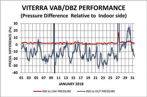
To monitor the performance of VAB/DBZ, the sensors installed on and in the exterior walls measured the temperature, RH, and the air pressure difference across two planes of the exterior walls. Specifically, measurements of temperature and RH were obtained near the cladding surface, in the exterior wall cavity, and the indoor side of the indoor finish. The air pressure differences were measured from indoor to wall cavity, wall cavity to outdoor, and from indoor to the outdoor side.
Sign up for our weekly newsletter
Construction Canada weekly newsletters give the latest AEC industry news for those who build, design, engineer, specify, renovate or operate in the built environment.
Related Products & Services

Read the Latest Issue