Using ground-penetrating radar with concrete
Nancy Walker, of New Jersey-based Atlantic Subsurface Imaging, is a proponent of the new proposed CSDA standards, saying they promote professionalism in concrete cutting.
“The certification application process gave us an opportunity to do a self-assessment in areas such as safety, training, quality control, customer satisfaction, and compliance management,” she explains. “Overall, the CSDA company certification has resulted in a more professional approach across the company and a greater sense of pride taken by all for the work they and the company are accomplishing.”
Among other items, Walker says proposed standards will include concrete scanning best practices that can be used when developing a scope of work that requires concrete cutting.
The co-chair of the CSDA Imaging Committee, Emily Hammer, agrees with the need to develop uniform standards—for the past three years, she has been working on updating imaging best practices and incorporating them into CSDA industry standards. Her firm, Hard Rock Technologies, also uses practices outlined in the association’s Ground Penetrating Radar for Concrete Imaging and Depiction/Marking of Existing Subsurface Embedments, which provides an overview and methodology for properly marking out embedments found with GPR. The guidance includes the preferred marking colour, use of any temporary marks, marking of exclusion zones on either side of GPR scanning areas, and how to mark depths.
The importance of maintaining good communication with imaging contactors
It is important concrete cutters, and other relevant members of the project team, maintain good communication with the imaging contractor to avoid misinterpretations of data, says Hammer.
She explains the area is first laid out by the contractor and then her firm scans the concrete.
“Without the GPR, it’s just a concrete floor, but with the GPR equipment, we are able to gather the data and transfer it onto the slab in a way that communicates what is going on in the slab. Then we communicate verbally with the contractor on what the marks mean. This may cause a changed layout or confirm that the original location was acceptable.”
There must be communication between the two on what the markings mean because there is not yet a standardized system.
“My marks look different from another contractor’s,” says Hammer. “CSDA is also trying to standardize the markings, but even when that is done, communication would still be important so all parties have an understanding of what is going on.”
She notes that the new proposed CSDA standards call for the imaging contractor to do a follow-up walk through on the jobsite to ensure the job is done to their understanding.
Conclusion
Concrete cutting firms need to know the location of rebar, post-tension cables, and conduits within concrete structures prior to drilling, cutting, coring, trenching, or digging. Not doing so opens up the firms and their customers to damage claims and potential safety hazards. Using ground-penetrating radar—and following CSDA’s imaging standards—is the best way to avoid delays and ensure safety.
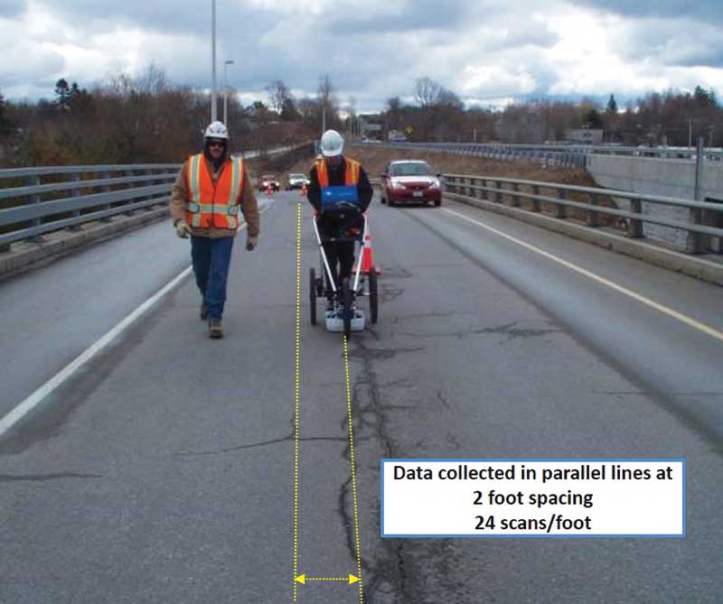
GPR’s ability to ‘see’ what is inside concrete goes far beyond cutting applications, of course. It also enables buildings and bridges to be inspected without being damaged to ensure those structures remain durable. Often, the initial costs of the radar technology are vastly outweighed by the savings afforded by the knowledge the processes provide.
| SLEUTHING A BRIDGE’S STRUCTURAL SUCCESS |
|
Aside from ground-penetrating radar (GPR), there is a wide array of bridge inspection tools being used around the country, alone or in combination, non-destructive or destructive. Acoustical techniques Acoustical methods are advantageous because they are inexpensive and easy to do with limited training. Typically, the worker will locate areas of deterioration just by the tone and will mark the area with a circle of spray paint—the areas are then registered later by another employee who takes a picture or lays out a grid to map them. The technique is basically designed to get real-time answers to delamination locations. The method’s drawbacks include the fact it does not work on bridges with asphalt overlays, and different users may provide different delamination maps due to hearing biases. Outside noise (e.g. traffic) can affect the results. It is impossible to get 100 per cent repeatable results with different people conducting the inspections. Also, the technique only produces a map of existing delaminations, which occur after the rebar is significantly corroded. Deterioration that has not yet led to delaminations is not mapped, making the technique inappropriate for planning more proactive repairs. Half-cell potential Unfortunately, the method cannot be done on bridges with asphalt overlays. Bare concrete is required, and using this process requires closing down the bridge deck, which can have a negative effect on traffic. Half-cell potential also requires quite a bit of time to complete, as discrete measurements are done on a grid pattern. This method is probably best used in situations where one already knows the bridge deck requires repairs and is trying to determine where repairs are needed and what kind of repair is necessary. It can help determine when one needs to totally remove the deck or do in-place cut and patch repairs. Infrared Visual inspection Visual inspection is also the least efficient maintenance method, since it addresses problems only after they have resulted in the most damage and cost the most to fix. It is analogous to a leaky roof or water pipe—better to fix the roof or pipe before the leaking water ruins everything around it. Coring and chipping |
 Bruno Silla is an application specialist for Geophysical Survey Systems Inc. (GSSI), a ground-penetrating radar (GPR) firm. He has extensive experience with GPR in the concrete construction field, and was an operation specialist in the U.S. Navy, with workstations such as surface-to-surface and surface-to-air radar mapping and detection. Silla actively participates in several professional concrete construction associations and has recently been elected as co-chair of the Concrete Sawing and Drilling Association’s (CSDA’s) Next Generation Committee. He can be reached at sillab@geophysical.com.
 Roger Roberts is lead research engineer at GSSI, and has been working with GPR applications on roadways, bridges, and other concrete infrastructure for more than 20 years. He has authored and co-authored numerous papers presented at conferences, and has been awarded four patents related to GPR use for bridge inspection and/or rebar detection. Roberts can be reached at roger@geophysical.com.
Sign up for our weekly newsletter
Construction Canada weekly newsletters give the latest AEC industry news for those who build, design, engineer, specify, renovate or operate in the built environment.
Products & Services


Read the Latest Issue