Understanding masonry veneer construction
By Kenneth M. Itle, AIA, Mike Ford, and Timothy Penich
Contemporary masonry veneer construction consists of a single wythe of masonry, such as brick or stone, mechanically anchored to a backup structure, typically either wood or light-gauge steel framing or concrete masonry units (CMUs). The veneer is supported laterally by the backup structure and bears on the foundation or a shelf angle. Veneer construction incorporates an air space between the masonry and the backup wall to deter water penetration into the building and reduce heat transmission when fitted with continuous insulation (c.i.). Water-resistant barriers (WRBs), flashings, weeps, and drainage systems are also installed to facilitate drainage. WRBs can also serve as air barriers for the exterior wall assembly. Masonry veneer wall systems are composed of many different materials. Thus, masonry veneer construction must be designed to accommodate differential movement.
Code requirements for masonry veneer walls are outlined in CSA S304, Design of Masonry Structures. Additional guidance for specifiers is provided in CSA A371, Masonry Construction for Buildings. The Canada Masonry Design Centre (CMDC) offers technical resources on masonry veneer design based on the National Building Code of Canada (NBC). The Brick Industry Association (BIA) has authored various technical notes on brick construction to provide guidance on individual materials and general construction of masonry veneer systems. They serve as useful references. Finally, CSA and ASTM standards define the characteristics of masonry materials.
Brick
Brick is manufactured from naturally occurring substances that are fired. Typically, test data including absorption, saturation coefficient, compressive strength, efflorescence, and initial rate of absorption can be obtained from brick manufacturers and suppliers. Brick testing is conducted in accordance with CAN/CSA-A82, Fired Masonry Brick Made from Clay or Shale. This standard also defines two grades of brick, exterior grade (EG) and interior grade (IG). As implied by the terminology, only EG brick should be used where the masonry may be exposed to exterior weather including freeze-thaw cycles.
The physical requirements for each grade include minimum compressive strength and maximum water absorption and saturation coefficient. The saturation coefficient is a ratio of the rate of absorption by 24-hour submersion in cold water to five-hour submersion in boiling water. CSA A82 states the saturation coefficient requirement does not apply if the 24-hour cold water absorption of the five tested brick units does not exceed 8 per cent. An alternative to test five brick specimens for 50 cycles of freezing and thawing is also defined in the standard.
Initial rate of absorption and efflorescence are also included in the test data. Initial rate of absorption data should be requested from the brick manufacturer, as this property is used to assist in mortar selection as well as the installation process. For example, brick with a high initial rate of absorption frequently experience poor bond and mortar separations due to water being drawn out of the mortar during placement, especially during hot, dry weather. This can be mitigated by wetting brick just before they are placed; however, thoroughly soaking bricks for three to 24 hours prior to placement is recommended so water can be better distributed throughout the unit. The soaked bricks must be kept above freezing.
Results from efflorescence testing are also included in the manufacturer’s data. The specified rating for efflorescence should be “not effloresced.”
Three brick types are outlined in CSA A82: Type S, Type X, and Type A. Type S is brick for general use and is the most commonly specified. Type X is for projects requiring a high degree of precision and low variation in size; and Type A is meant for producing architectural effects resulting from non-uniformity in the size and texture of individual brick units. CSA A82 outlines physical requirements for each brick type.
While selecting brick with the appropriate grade is important, it is also crucial to provide an effective water management system to control water that enters the wall cavity through the veneer, to further ensure a successful wall assembly.
Mortar
Mortar is typically composed of cement, hydrated lime, and sand, mixed with water; admixtures and pigments are used as well. CAN/CSA A179, Mortar and Grout for Unit Masonry, outlines standards to reference when specifying mortar.
Cement-lime mortar, masonry cement, and mortar cement can be used in mortar. Portland cement is blended with hydrated lime to produce cement-lime mortar. Masonry cement contains Portland or blended hydraulic cement and limestone or lime. Mortar cements are similar to masonry cements in content but there are controls on air content and minimum strength requirements in the former. Both masonry cement and mortar cement may contain additives specific to each manufacturer, therefore, careful review of product data and safety data sheets is necessary.
ASTM C207, Standard Specification for Hydrated Lime for Masonry Purposes, outlines four types of hydrated lime:
- N – normal hydrated lime
- S – special hydrated lime
- NA – normal air-entraining hydrated lime
- SA – special air-entraining hydrated lime
It should be noted some building codes prohibit the use of air-entraining materials in mortar due to the resulting reduction in bond and compressive strength. Therefore, Types NA and SA should not be specified for masonry mortar. The special types of hydrated lime (S and SA) offer advantages of higher early plasticity and water retentivity. For these reasons, Type S is the most commonly specified hydrated lime type for masonry mortar. Depending on the amount of lime used in the mortar mix, bond, workability, water retention, and elasticity can be adjusted.
Sand or aggregate is a filler material and it helps reduce shrinkage in mortar. Different sands or coloured aggregate can also be used to achieve a specific texture or colour. CSA A179 defines the requirements for aggregate and states aggregate for use in mortar shall consist of “hard, strong, and durable mineral particles that are free of injurious amounts of saline, alkaline, organic, and other deleterious substances.”
Admixtures can result in a change of properties, such as increased workability or a decrease in setting time, and they can also be used to achieve a specific colour. Water-repellant admixtures are commonly specified for mortar when concrete masonry is used for the veneer. They need to be co-ordinated with other water-repellants employed in CMUs. Cold-weather admixtures to allow installation of masonry at temperatures below 4.4 C (40 F) can be used with caution, although specifiers should carefully review the effect on future durability and performance.
Under no circumstances should calcium chloride or admixtures containing chloride ions be used due to the risk of accelerated corrosion for any metal components in contact with the masonry. Any type of admixture is to be used, the same material should be employed consistently across the project for appearance and performance consistency.
Pigments can be employed to achieve a certain colour, although coloured aggregate may be preferable for distinctive or bold hues. The use of an excessive proportion of pigment can also reduce strength or durability.
In addition to mortar components, CSA A179 outlines two mortar types and recommends the conditions they should be used in. The two types of mortar defined are Type N and Type S. These types have different minimum strength, water retention, and air content requirements depending on the type of cement used in the mix. Type N mortar is recommended for loadbearing walls and exterior veneer wall construction.
The mortar ingredients (e.g. Portland cement, hydrated lime, sand, and any pigments or admixtures) can be blended on-site, although quality control (QC) to ensure consistency between batches can be challenging. Alternately, custom preblended dry mixes with all ingredients for the project are readily available, and these mixes only require the addition of water onsite. Product data should be also reviewed to understand any admixtures in the mix and to ensure the constituents and characteristics of the preblended mortar meet the project requirements.
In addition to selecting the appropriate mortar based on how or where it will be used, it is also important to evaluate how the selected mortar will interact with the selected brick when specifying a mortar type. For example, mortar typically bonds best with masonry units with a moderate initial rate of absorption.
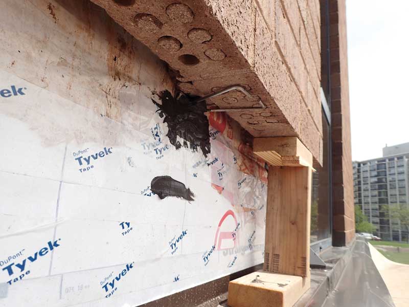
Veneer ties and anchors
In a veneer wall system, the ties are intended to connect the backup wall construction to the outer wythe of masonry, transfer lateral loads, and accommodate in-plane differential movement. An effective veneer anchor system should be securely tied to the backup construction and veneer masonry, have sufficient stiffness to accommodate lateral loads, and be corrosion-resistant. Minimum requirements for masonry connectors are specified in CSA A370, Connectors for Masonry.
There are many types of veneer tie and anchor systems for new construction including:
- Corrugated metal and rectangular ties, referred to as unit ties.
- Ladder and truss-type ties, referred to as horizontal joint reinforcing.
- Various types of adjustable veneer ties.
Corrugated metal ties are not recommended due to the width of the ties that may provide an avenue for moisture to bridge the air space. They are more susceptible to corrosion than wire ties and sometimes experience an insufficient lateral support, inadequate accommodation of vertical movement, and lack of bond with mortar at joints.
Rectangular, ladder- and truss-type veneer ties are best suited for multi-wythe masonry construction. With these masonry tie systems, the CMU backup wall and veneer can be built simultaneously with ties installed at the bed joints. These ties provide strength and stiffness to accommodate lateral forces and can potentially restrict expected in-plane movement, or deform under service loading.
Adjustable veneer anchors are a two-piece system, and commonly include eye and pintle, dovetail, and slotted systems. Adjustable systems generally allow for construction of the backup assembly first, followed by the installation of a masonry veneer. Adjustable ties can also accommodate larger in-plane differential movement and construction tolerances.
When specifying and detailing lateral anchors, hot-dipped galvanized steel in conformance with ASTM A153, Standard Specification for Zinc Coating (Hot-Dip) on Iron and Steel Hardware are required by code for exterior wall systems. In more corrosive environments or areas where wall systems are susceptible to excessive water penetration, stainless steel ties in conformance with ASTM A580, Standard Specification for Stainless Steel Wire, are recommended.
Masonry wall ties should be sized to fit the width of the mortar joints and wall construction, and spaced to accommodate lateral loads. Standard wire diameters for masonry ties are W1.7 (3.76 mm [0.1483 in.]) and W2.8 (5-mm [0.19-in.] diameter wire). The allowable wire diameter for masonry ties is limited to half the mortar joint width per CSA S304. The larger 5-mm [0.19-in.] wire will meet this requirement in a standard 10 mm (0.40 in.) joint width; however, given the typical tolerances in masonry construction, the smaller diameter wire may be recommended to allow for sufficient mortar coverage in as-built joints that may be slightly less than 10 mm (0.40 in.). Veneer ties and anchors should be sized so they span the cavity space and extend a minimum of half the depth of the masonry veneer unit. BIA suggests a minimum embedment of 38 mm (1.5 in.) with a minimum cover of 16 mm (0.62 in.) at the exterior face of the masonry veneer for hot-dipped galvanized ties.
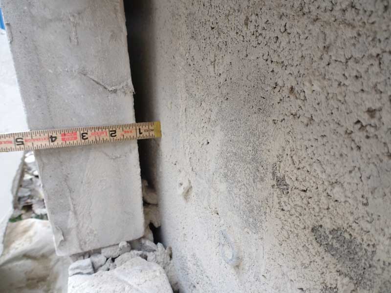
Drainage cavity
Although masonry is a highly durable material, it is not inherently waterproof. Masonry materials will absorb moisture from precipitation and only gradually dry as ambient conditions change. For this reason, a masonry veneer must be isolated from the backup construction by an air cavity.
The cavity in a veneer wall system provides an avenue to drain water entering the wall system. It consists of an air space and WRB, and may also include a thermal control layer such as rigid insulation and a drainage mat. Veneer ties span across the drainage cavity, and the width of the air space is measured as the distance between the back of the masonry veneer to the face of the backup wall or insulation. Part 9 of the NBC requires the cavity width to be at least 50 mm (2 in.) and not greater than 150 mm (5.9 in.). CSA S304 also limits the cavity width to not more than 150 mm (5.9 in.).
For wider drainage cavities, more robust and frequent spacing of veneer ties is required to transfer lateral loads, or a project-specific design for the ties must be developed.
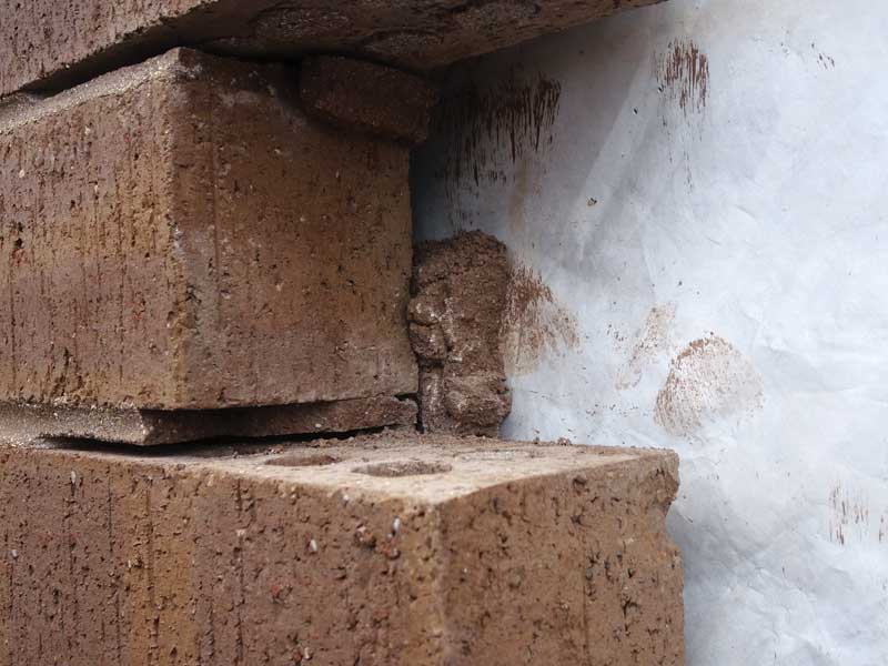
The effectiveness of the drainage cavity depends on the continuity of the air space and WRB. Mortar bridging, resulting from excessive mortar droppings, interrupts the air space and can create avenues for water to reach the backup construction. A narrow air cavity, changes in the depth of the veneer masonry, or misalignment of insulation in the drainage cavity may cause the formation of mortar bridges. The use of mortar net-type products is not a panacea, and good practice should still be followed to limit accumulation of mortar in the air space. It is recommended to mechanically fasten or adhere the rigid insulation in the drainage cavity to the backup.
WRB is installed on the exterior surface of the backup assembly, and may be fluid-applied, self-adhered, or mechanically fastened. The barrier should be free of defects such as wrinkles and open joints (fish mouths) that may promote mortar bridging or allow water to infiltrate to the interior. If self-adhered or mechanically fastened, the edges of the membrane should be shingle lapped at least
150 mm (6 in.). Ideally, screw heads and penetrations in the WRB should be sealed with a compatible sealant to maintain the continuity of the barrier. While not preferred, water-resistant facing of sheathing or rigid insulation may be used if all penetrations, edges, and joints are properly taped and sealed.
For narrower air spaces, where there is a greater probability of mortar bridging within the cavity, drainage mats, mortar nets, and other drainage systems are recommended. These systems are most effective when installed at the full height of the wall and can provide a clear path for air and water movement in the wall cavity. For drainage mats, the drainage portion of the mat should be oriented to the cavity face of the masonry veneer.
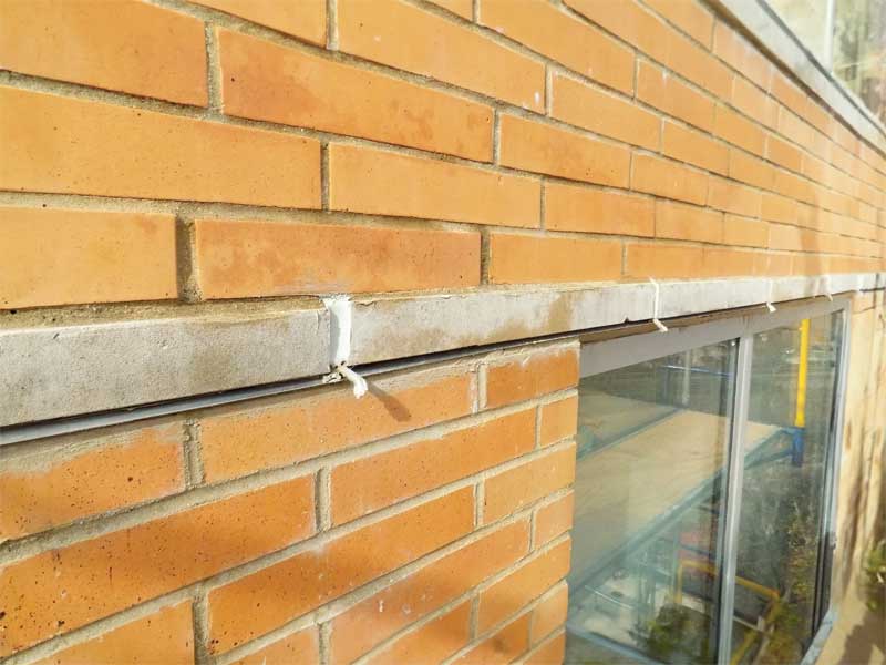
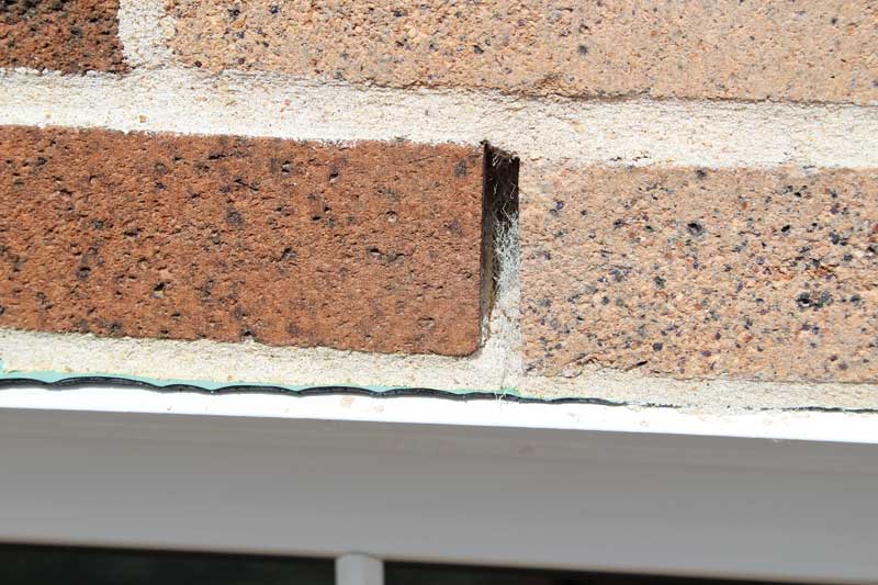
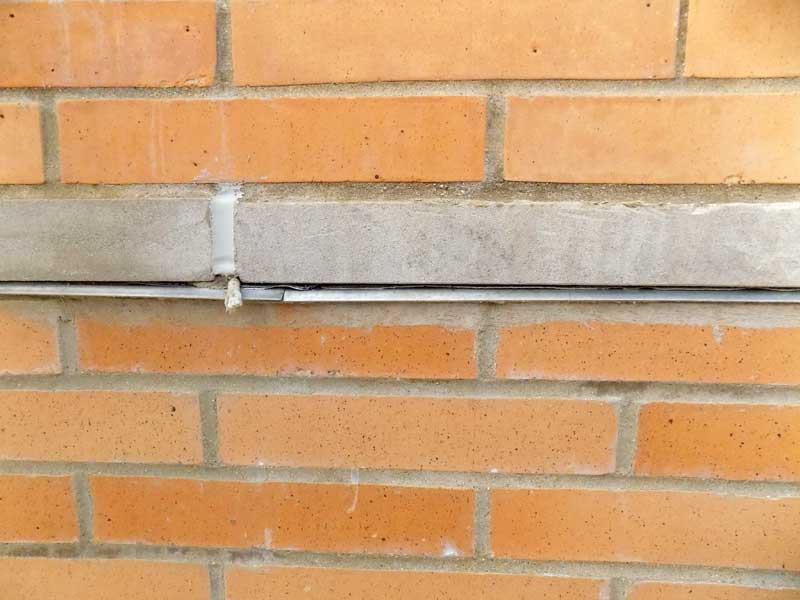
Flashings and weeps
At all horizontal terminations or discontinuities in masonry veneer construction, flashings must be provided to ensure moisture in the masonry and drainage cavity is directed to the exterior. Common flashing materials include metal (e.g. stainless steel or copper) or membrane (e.g. rubberized asphalt or butyl-based materials). Fluid-applied and prefabricated flashings are also available. Metal flashings can be made continuous by soldering adjacent sections or by lapping and fully bedding laps in transverse lines of butyl sealant. Rubberized flashings are lapped and sealed with a compatible product. Although other materials, such as laminated copper flashing, asphalt-coated copper fabric flashing, ethylene propylene diene monomer (EPDM) rubber, thermoplastic, or polyvinyl chloride (PVC) are available for flashings, they may be more prone to damage during construction, making it more challenging to form watertight seams between sections of flashing.
Flashing materials in a veneer system need to bridge across the cavity to integrate with the WRB at the back of the cavity or to terminate into the substrate. At the point where the flashing crosses the cavity, flexible materials may be prone to sagging or puckering, creating valleys where water can collect. Also, it can be challenging to make the seams between flashing pieces watertight at the cavity. For these reasons, rigid metal flashings are preferred, especially as a flashing pan to span the cavity.
The front edge of the flashing should extend beyond the face of the veneer with a drip edge, so water draining from the flashing is not allowed to run back onto the masonry or other materials below. Since rubberized flashing materials are generally unstable in UV light, these flashing materials should be held back at least 12 mm (0.5 in.) from the exposed face of the veneer and a stainless-steel or similar non-corroding drip edge provided to form the termination of the flashing system. The back edge of the flashing system should be secured to the backup, typically with a termination bar or mechanical fasteners. If a sheet-type WRB is used, the barrier materials should be shingle-lapped into the flashing assembly and fully sealed.
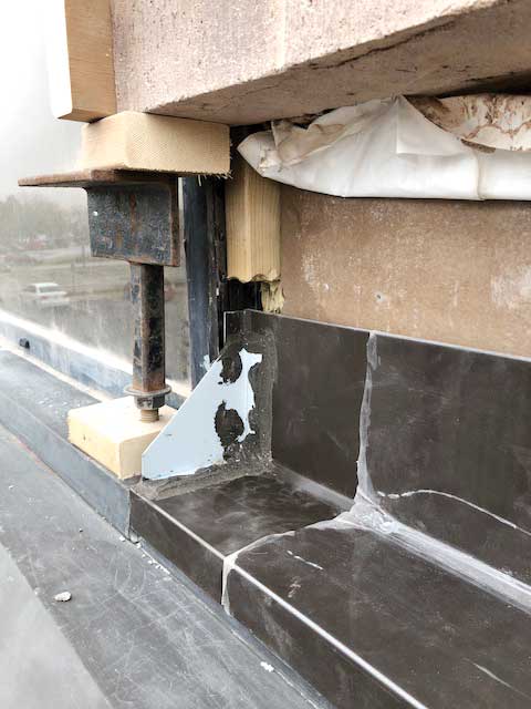
An end dam must be provided wherever a flashing terminates horizontally, such as at the end of a window lintel or shelf angle to better manage water within the cavity and direct it to the exterior. Without an end dam, water on the flashing may drain from the back corner, creating a concentration of water within the cavity that can saturate adjacent materials.
To ensure proper drainage from flashings, weeps or vents should be provided, a cotton or synthetic rope wicks, either with or without plastic tubes, may be used. Open gaps without a wick or plastic vent should be avoided, as these openings can permit the entry of vermin into the cavity. Open gaps also are less effective at removing water from the cavity than weeps or rope wicks that can help draw water out. These types of wicks must be placed by the mason within the head joints in the first course of masonry above the flashing and should be long enough to extend from the outer face of the veneer to the back of the cavity. Cellular plastic or aluminum cell vents sized to fit exactly within a single head joint are another option, and are available in many colours to minimize their visual impact. Rope wicks should be spaced at 400 mm (16 in.) on centre. Weep vents can be spaced at 600 mm (24 in.) on centre.
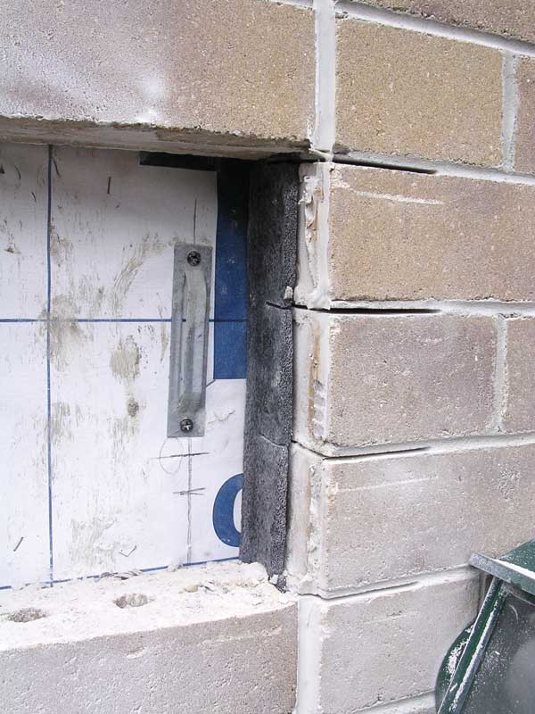
Control and expansion joints
For masonry veneers, movement related to thermal and moisture changes are key considerations. The code-defined coefficient for thermal movement of clay masonry equates to about 12 mm (0.5 in.) for a 30-m (100-ft) long wall experiencing 38 C (68 F) of temperature change. The equivalent value for concrete masonry is slightly higher. As a result, differential thermal movement between the materials of 1.6 to 4.8 mm (0.06 to 0.18 in.) is possible over a 30-m (100-ft) length.
Moisture-related masonry movements raise concerns related to long-term, irreversible volume changes. Clay masonry units are at their smallest size when removed from the kiln and first installed. The units will slowly and irreversibly expand over time as they absorb ambient moisture. The expansion is most rapid for the first year in service and decreases to a negligible rate after 10 to 20 years. A challenge in masonry design is that other commonly used building materials, particularly concrete and wood, experience irreversible shrinkage while in service, so the relative increase in size in a clay masonry veneer compared to the size of the underlying wood or concrete structure may be significant.
Control and expansion joints are used to accommodate movements resulting from these volume changes. Joints are also needed at changes in the architectural or structural geometry where cracks are likely to form. In veneers, vertical joints should be spaced at approximately 8-m (25-ft) intervals in walls without openings, at offsets or near building corners, door openings and window jambs, and at any joints in the underlying structure. Horizontal joints should be provided at every floor level in multi-storey construction. The minimum size of the joint needed can be determined by reference to the coefficients of thermal and moisture expansion for the various materials, the expected temperature change for the facade surface (which may be 49 C [88 F] or more), and the size of the masonry panel.
Conclusion
Contemporary masonry veneer wall systems offer design flexibility, means of addressing water penetration, and ease of construction. They incorporate a wide range of materials and systems including masonry, mortars, masonry ties, water-resistant barriers (WRBs), air barriers, insulation, flashings, and control and expansion joints. As such, the effectiveness of masonry veneer wall systems is dependent on material specification, attention to design and detailing, and proper construction procedures.
Authors
 Kenneth Itle, AIA, is an architect and associate principal with Wiss, Janney, Elstner Associates (WJE) in Northbrook, Ill. He specializes in historic preservation and the assessment and repair of masonry systems. Itle can be reached at kitle@wje.com.
 Mike Ford, AIA, is an architect and senior associate with WJE’s Northbrook, Ill., office, specializing in historic preservation and the assessment and repair of existing buildings. He can be reached at mford@wje.com.
 Timothy Penich, AIA, is an architect and senior associate with WJE’s Northbrook, Ill., office, specializing in historic preservation. His work also includes condition surveys and the preparation of repair documents relating to masonry and roofing and waterproofing. He can be reached at tpenich@wje.com.
Sign up for our weekly newsletter
Construction Canada weekly newsletters give the latest AEC industry news for those who build, design, engineer, specify, renovate or operate in the built environment.
Products & Services


Read the Latest Issue