The Leaning Towers of Vegas: Engineering the Veer Towers
By Neb Erakovic, M.A.Sc., P.Eng., and Terry Dawson, B.Eng., P.Eng.
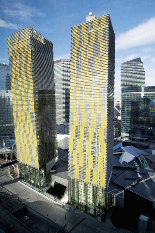
The Veer Towers are a pair of residential high-rises centred in the prestigious CityCenter development located between Bellagio and Monte Carlo on the Las Vegas Strip. With each leaning at opposing five-degree angles from the vertical, the twin towers house a total of 670 condominium units with rooftop amenity spaces and tall podium lobbies. The defining architectural characteristic of these 37-storey, 146-m (480-ft) tall towers, these leans required the sophisticated application of conventionally reinforced and post-tensioned concrete to the structural systems. (The authors would like to thank MGM Mirage and Infinity World Development Corp., a subsidiary of Dubai World (owners), Gensler (executive architect), Murphy/Jahn Architects (design architect), AAI Architects (architect of record), Tishman Construction Corp (executive construction manager), Perini Building Company (general contractor), Dywidag Systems International USA (post-tensioning subcontractor), Flack+Kurtz (mechanical, electrical, and plumbing engineers of record), Dianna Wong Architecture + Design (interior designer), Hamilton Anderson Associates (interior design architect of record), Michael Meschino, Frank Martinovic, Kyle Cossette, and everyone else who contributed to the success of this project).
The challenge of designing stable, leaning towers was overcome by a team of engineers from Toronto and Las Vegas (including this article’s authors) through the consideration and extensive analyses of all factors. Construction challenges resulting from the leans, structural features, and fast-track construction process were resolved with collaboration between the engineers and contractors.
Leaning effects
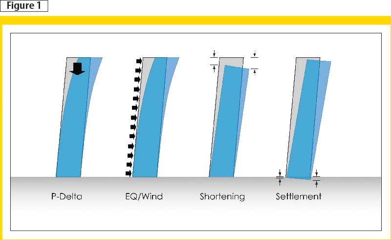
Numerous factors compete in an attempt to increase the towers’ leans beyond the intended architectural geometry. These factors, which are illustrated in Figure 1, include:
- the eccentricity of the weight found at the tops of the buildings;
- lateral earthquake and wind loads;
- differential axial shortening of vertical structural elements; and
- differential foundation settlement.
Veer Towers’ structural design ensures they remain stable, while their leans stay within a controlled range at all times. Building movements are kept within acceptable code limits to prevent damage to non-structural elements. The result is the achievement of comparable performance to ordinary vertical buildings.
Eccentricity of building weight
Due to the leans, the weight of the upper floors is eccentric to the vertical centreline of each tower (Figure 2). Known as the ‘P-delta effect,’ this eccentricity causes the top of the building to move toward the eccentric weight imposing permanent lateral shears and overturning moments. These forces try to push the towers further over in the direction of their leans.
Earthquake loading
The high seismic hazard in Las Vegas, combined with the tall height and weight of the reinforced concrete towers, makes earthquake-loading more critical than high winds when it comes to the system for resisting lateral forces. Due to reinforced concrete shear wall stiffness and strength, a significant level of ductility cannot efficiently be used to reduce the earthquake design forces, so ordinary ductility reinforced concrete shear walls were employed.
When an earthquake’s ground-shaking direction coincides with the direction of one of the tower’s leans, the effect on the lateral load resisting system is critical—the permanent and transient lateral shears and overturning moments become additive. If the side the tower leans toward is considered the ‘down’ side, the vertical compression is increased on that side while on the opposite ‘up’ side, net vertical tension may occur.
Differential axial shortening
Although there are no explicit code limits, responsible engineering design requires assessment of potential differential axial shortening effects for reinforced concrete buildings taller than 35 storeys. Differences in vertical stresses between vertical reinforced concrete elements cause those elements to axially shorten by different rates and amounts.
For the reinforced concrete, there are three types of shortening that occur:
- elastic (due to axial stress);
- creep (due to long-term sustained axial stress); and
- shrinkage (due to concrete drying as it cures).
Shortening differences can lead to undesirable cracking of non-structural elements, such as cladding and partitions; it can also cause floor slabs to slope. In vertical buildings, columns tend to have higher compression stress than walls, and interior columns often have higher compression stress than perimeter columns. The propensity for differential axial shortening between these vertical elements (due to these stress differences) is amplified for leaning towers because the vertical compression stresses are higher on the ‘down’ side than the ‘up.’ Also, if the ‘down’ side shortens more than the ‘up’ side, then the tops of the towers move laterally. This increases the P-delta eccentricity and the leans.
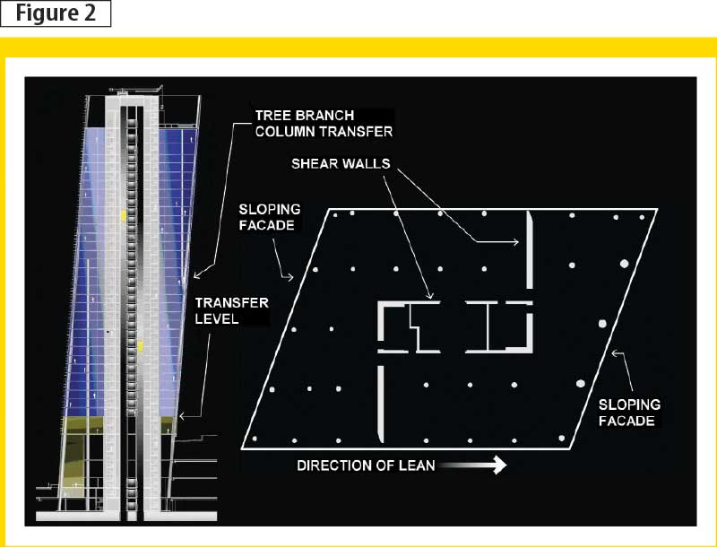
Image courtesy Murphy/Jahn Architects
Differential settlement
A system of drilled reinforced concrete foundation shafts was used to support the towers and limit differential building settlements to acceptable levels. To resist vertical loads, the shafts rely on end-bearing onto the dense sand below and surface friction against the sand down the sides of the shafts. The vertical compressive pressure on the sand is higher on the ‘down’ side and lower on the ‘up’ side, leading to differential settlement. Similarly to differential axial shortening, this causes the tops of the towers to move laterally, increasing the leans.
Lateral load resisting system
The combined impact of P-delta effects, permanent loads, transient earthquake loads, differential axial shortening, and differential settlement were extensively studied for impact on the tower leans. As a result, stiff and strong coupled shear wall systems were needed for each tower. Conventionally reinforced concrete shear walls (as seen in Figure 2) form a large, boxed, Z-shaped megacore at the centre of each tower.
Structural features
The buildings’ architectural complexity necessitated structural components such as branch column transfers, inclined composite lobby columns, and post-tensioned column transfer beams.
Images courtesy Yolles, a CH2M HILL Company
Branch column transfers
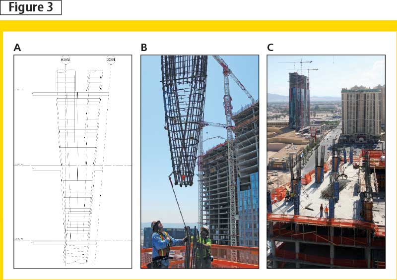
Although shear walls and internal tower columns are vertical, the leaning geometry of the towers shifts each floor plate over in relation to the floor plate below. Over the 146-m (480-ft) height of the 37 storeys, the floor plates shift a total of 10.1 m (35 ft) in the north/south direction. To follow this shift, inclined columns are located on the sloping north and south building façades. At the sixth, 19th, and 32nd floors, column transfers are required where the inclined north and south façade columns join internal columns set in location to suit architectural layouts and to maintain feasible spans for the 203-mm (8-in.) thick flat reinforced concrete floor slabs.
Due to the leaning geometry of the towers, the reinforced concrete column transfers are tree-branch-shaped as shown in Figure 3. More reinforcing steel is added to the floor slabs to resist the additional horizontal diaphragm forces.
Inclined composite lobby columns
The residential lobbies of both towers are located at the sloping south façades adjacent to the elevated roadway. These 24.4-m (80-ft) tall lobbies feature exposed reinforced concrete columns inclined to follow the tower leans (Figure 4). Located at the base of the towers, the columns have significant axial forces—particularly the West Tower, which has a lobby situated on the ‘down’ side.
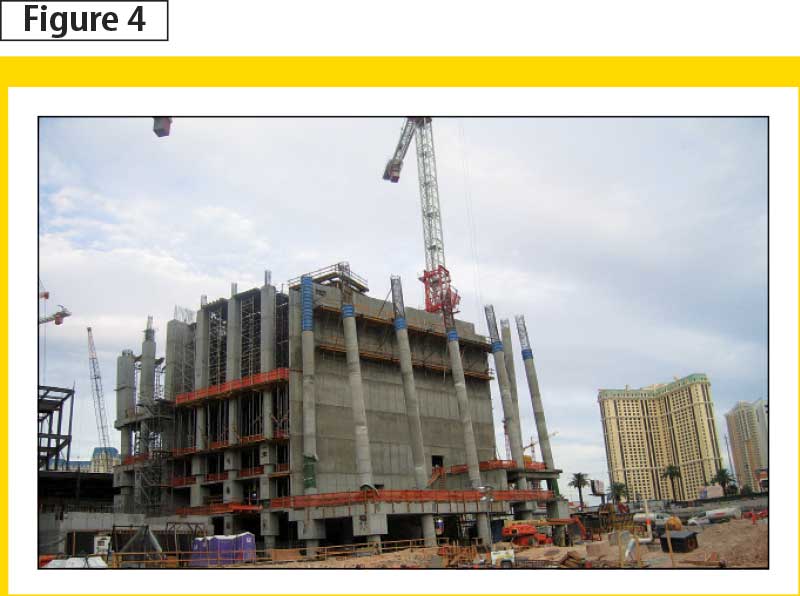
To minimize column sizes and improve slenderness behaviour due to their tall height, composite columns with large embedded ‘W’ structural steel members encircled with reinforcing steel were used. Temporary shoring was required to hold the columns in their correct position during construction until the tops of the columns could be tied into the transfer floor level above the podium.
To further improve column slenderness, the columns are partially fixed against rotation with the large post-tensioned transfer beams at the top and large conventionally reinforced concrete beams at the base. As the columns are inclined, thorough design checks were required to confirm satisfactory interaction of axial buckling with slenderness, lateral deflections, and P-delta effects.
Post-tensioned column transfer beams
Between the lower podium and upper condominium apartment levels, tower column loads are transferred to podium columns that continue down to the foundation. Eight major post-tensioned (PT) transfer beams are located here, supporting the 34 storeys of the towers above.
 Due to space planning requirements at the tower bases, a number of upper columns are terminated at the transfer floor level (Figure 2 shows the location). The transfer beams support these columns and transfer their loads to adjacent columns continuing down to the foundation. The parallelogram-shaped floor plate and architectural layout results in some transfer beams being supported on other transfer beams. This creates complex pre-stressing and reinforcement details; three large transfer beams intersect together at one location, for example. Also, supported and supporting columns are commonly offset from PT beam centrelines, creating secondary torsional forces that required the addition of perpendicular beams for restraint against rotation.
Shear and torsion analysis and design were conducted using Response-2000—a program developed by Evan Bentz, an associate professor at the University of Toronto (U of T). This freely available non-linear sectional analysis program considers the adverse effect of bending moment on shear capacity with interaction of torsion for a reinforced concrete section.
The large loads being transferred required high pre-stressing forces to be applied to the PT beams. Anchoring these forces at the ends of the beams meant adding a mesh of anchorage and bursting zone steel reinforcement as transverse stresses occur in the concrete due to the compression applied by the pre-stressing. Transfer stresses for these beams are typically 15 to 20 per cent of the compressive stress due to pre-stressing force.
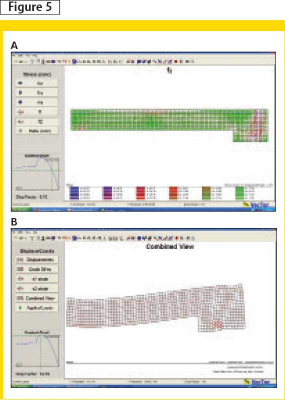
PT beam intersections create disturbed stress areas that extend approximately the beam depth away from the supporting beam’s face. These disturbed areas were assessed using VecTor2, which is another freely available U of T program, this one developed by Professor Frank Vecchio (Figure 5).
Pre-stressing of large PT transfer beams was completed in several stages to keep internal beam stresses within allowable limits as construction progresses to add more load to the beams. The staged pre-stressing considered:
- effects of losses in pre-stressing tension of the high-strength tendons over time;
- magnitude of construction loading, including timing of the application of cladding and finishes; and
- variation in concrete material properties as the concrete ages.
Images courtesy Vecchio
The post-tensioned transfer beams provided an effective solution to the architectural requirements by controlling deflections and cracking while providing high load-carrying capacity and minimized beam depths.
Project construction
In the past, construction in Las Vegas has generally been faster than many other North American cities; the pace at CityCenter represented a further acceleration. Although the local building industry includes many experienced reinforced concrete contractors, the CityCenter development challenged them to extend that experience to build more complex structures of higher architectural quality even quicker.
As mentioned, the geometry and structural features of these leaning towers is very complex; this meant the need for quality construction of formwork and concrete placement, close trade and logistical co-ordination with adjacent buildings, and accurate steel reinforcing fabrication and placement for congested structural elements.
Fast-track
Sequential tendering and a fast-track schedule were used to speed up the project’s design and construction phases. Once above the transfer floor level, a five-day typical pour cycle was applied for the conventionally reinforced 203-mm (8-in.) thick, parallelogram-shaped floor slabs. The typical condominium apartment level consists of about 1160 m2 (12,500 sf) of floor area. Figure 6 illustrates the rapid construction progress of Block C with Veer Towers in the centre.
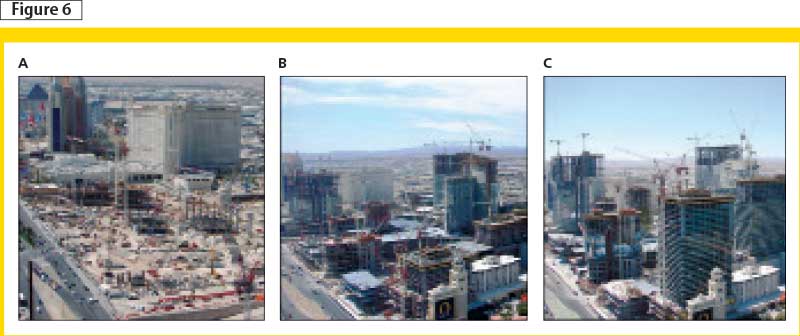
Photos courtesy Perini Building Company
Super-elevation
As a consideration of the numerous factors contributing to the buildings’ leans, both tower displacements and floor slab elevations were regularly monitored during construction. To allow for the anticipated shortening of columns and walls and for the anticipated settlement, each concrete floor slab is constructed slightly higher than the final intended design elevation by adjusting the formwork. This method of construction is known as ‘super elevation.’
Although design analyses indicating a preference to super-elevate by different amounts across each floor plate due to differential shortening and settlement, construction practicalities dictated a need for constant super elevations across each floor plate, varying linearly up the height of the towers. Floor levelling compound was applied in each condominium unit to mitigate this potential problem.
Photos courtesy Yolles, a CH2M HILL Company
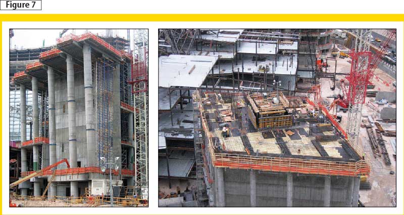
PT beam formwork
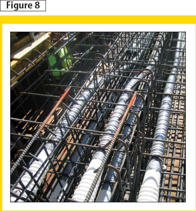
Figure 7 shows the elaborate cantilevered and suspended formwork for the transfer beams over the residential lobbies. Figure 8 illustrates the six draped PT tendons, arranged in two rows of three, across a typical PT transfer beam section.
Interfaces with adjacent buildings
With a retail building wrapping around the bases of both towers, there are numerous architecturally linked spaces between the three buildings. Their interfaces are carefully detailed with expansion joints to accommodate differential movements between buildings due to:
- settlements and shortening;
- lateral movements due to earthquake and wind loads; and
- thermal expansion and contraction.
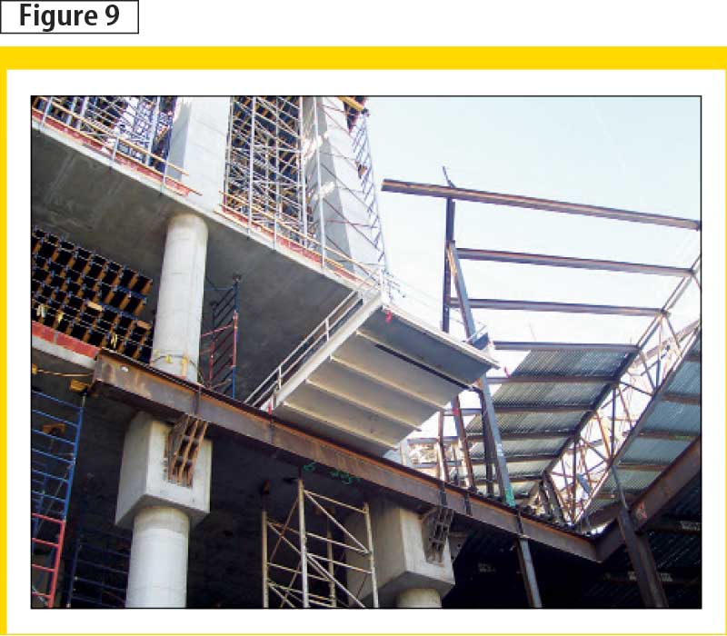
The retail building is predominantly framed in structural steel with reinforced concrete shear walls for stair and elevator cores. Many long-span structural steel beams required support at the perimeter of the Veer Tower podiums at floor levels and in between floor levels. Large reinforced concrete corbels (Figure 9) were added to the face of the tower columns to support bearing pads for the beams that accommodate differential movements between the two buildings. Final structural steel connections adjacent to the towers were made as late as possible during construction to mitigate movement effects by allowing a significant amount of shortening and settlement to occur beforehand.
Reinforcing detailing and placement
The unusual geometry of the towers created limited construction repetitiveness, and complex detailing of elements, such as:
- coupled shear walls;
- branch column transfers;
- inclined composite lobby columns; and
- PT beams.
Thick, heavily reinforced concrete shear walls were required on the ‘down’ sides of the towers while the net vertical tension in the shear walls on the ‘up’ sides required mechanically coupled vertical reinforcing over the full height of some of the walls. At branch column transfers, the joining circular columns required the fabrication of custom opening steel forms to suit the unique geometry and facilitate the placement of steel reinforcing.
At the bases of the inclined lobby columns, steel reinforcing was locally co-ordinated and displaced around the large baseplates of the W-section columns. To alleviate ‘congestion’ between heavily reinforced vertical elements and PT transfer beam pre-stressing anchors and end-reinforcing, transfer beams were extended through supporting walls and past supporting columns. Self-consolidating concrete (SCC) was used to improve concrete placement in locally congested reinforcing areas with Lenton terminators and couplers also used to develop and couple rebar to reduce congesting hooks and lap splices.
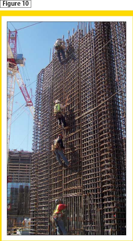
Figure 10 shows typical shear wall reinforcing for the tall podium floor-to-floor heights.
Conclusion
Conventionally reinforced and post-tensioned concrete was innovatively applied to the structural systems of the leaning Veer Towers. P-delta effects due to the eccentric weight of the tops of the towers, lateral loads, differential axial shortening of vertical elements, and differential settlement tend to increase the tower leans, requiring thorough design checks to ensure the intentional architectural leaning geometry is controlled.
Branch column transfers were necessary due to the leaning geometry of the reinforced concrete towers—this meant complex steel reinforcing detailing and formwork. Structural steel ‘W’ sections were embedded into tall, heavily loaded reinforced concrete columns to reduce column cross-section dimensions, and their slenderness buckling behaviour is improved with the addition of rotation restraining beams at top and bottom. Large, intersecting PT transfer beams with offset loads and supports were utilized to increase usable space below by terminating columns above and transferring their loads to adjacent columns and walls.
This fast-track project was continually monitored during construction to ensure the intended tower leans were not exceeded. Super-elevating construction techniques and expansion joint and connection detailing at the adjacent retail building is used to accommodate movements during and after construction. Reinforcing congestion in critical areas of the structure was mitigated with various techniques to achieve design needs while improving constructability.
The architectural success of the striking leaning Veer Towers relies on advanced structural engineering solutions using stiff and strong reinforced concrete lateral load-resisting systems to withstand a natural tendency to lean further than intended. Viewed from a plane landing or taking off from the nearby airport, a limousine on the Strip, or a window of the neighbouring hotels and restaurants, the dramatic leaning towers catch the eye and the imagination by showcasing a supreme application of concrete construction to high-rise buildings.
Neb Erakovic, M.A.Sc., P.Eng., is a principal in Yolles, a CH2M HILL Company’s Toronto office. He has successfully performed technical design and management roles on some of the firm’s largest and most notable buildings in Canada, the United States, and overseas. Erakovic’s work focuses on complex structures and collaboration with signature architects. Erakovic can be reached via e-mail at
neb.erakovic@ch2m.com.
Terry Dawson, B.Eng., P.Eng., is an associate in Yolles, a CH2M HILL Company’s Toronto office. Educated in New Zealand, he has worked on the design of technically challenging buildings and structures in Canada, New Zealand, the United Kingdom, and the United States, gaining wide-ranging, knowledgeable international experience. Dawson can be contacted via e-mail at terry.dawson@ch2m.com.
Sign up for our weekly newsletter
Construction Canada weekly newsletters give the latest AEC industry news for those who build, design, engineer, specify, renovate or operate in the built environment.
Products & Services


Read the Latest Issue