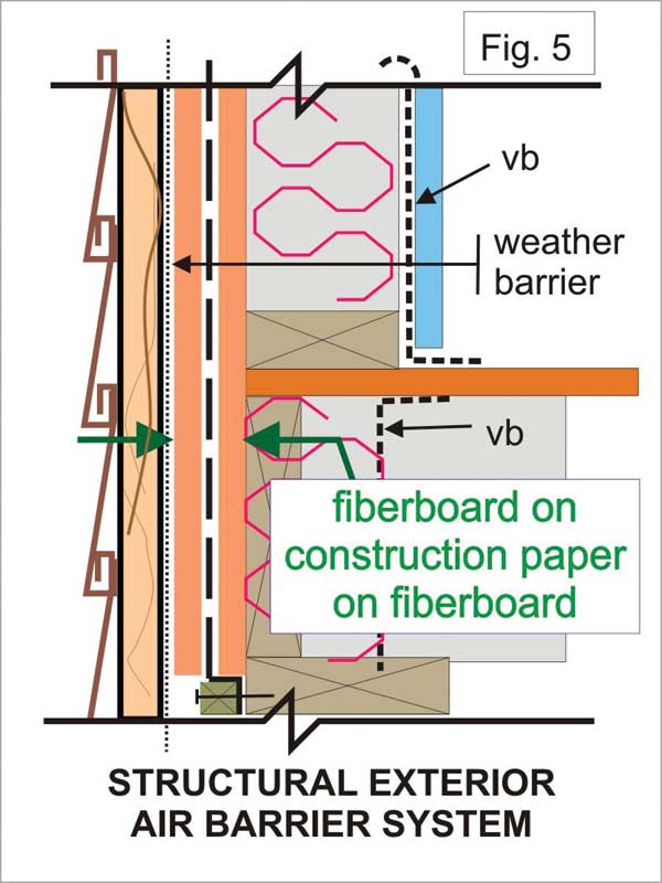
Structural Requirements of the Air Barrier Explained
Rigid paneling and solid materials
Rigid paneling and solid materials fair air barrier construction may or may not be air impermeable. But their rigidity is often the required attribute to create a structured air barrier assembly. Rigid panels are generally strong enough in flexure and or compression and tension to span cavities and be attached to the structural framing. If the panel air permeability is inadequate, then by combining a rigid panel with an air impermeable membrane or coating, the assembly can exhibit the necessary properties of a structured air barrier assembly. Rigid paneling and solid materials include, but are not limited to, plywood, gypsum board, particle board, ribbed sheet steel panels, concrete shear walls, precast panels, and more.
Joints and connections in the air barrier system
Joints and connection products are unique and important. Their properties not only comprise air impermeability, but include chemical compatibility with the materials to be joined, type of structural attachment for both sides of the joint and connection, flexibility to expand and contract with live load deflections, expansion and contraction due to temperature changes, resistance to high pressure loads, and long-term low pressure loads. Corner joints in buildings can be subject to two times the wind design load experienced by the wall. Materials for joints and connections include sealants excluding non-setting sealants, membranes, sheet aluminum, and sheet steel joint components and more.
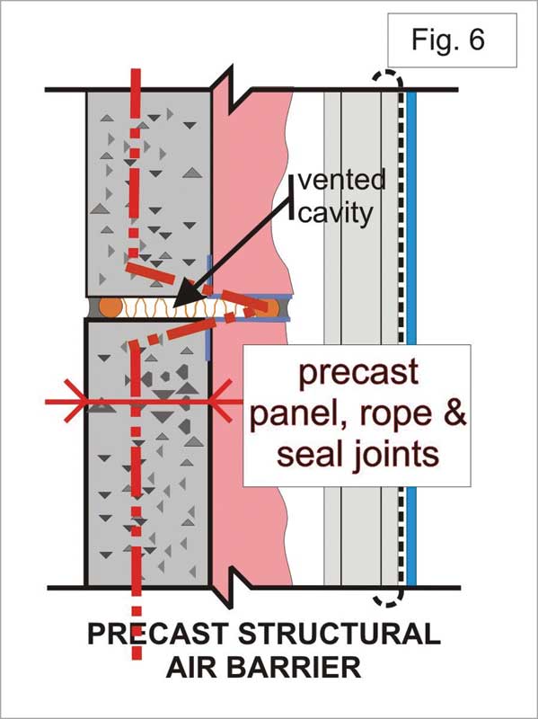
Cladding systems
Cladding systems can and do include air barrier characteristics and air leakage control performance criteria. For example, a precast clad building using the face seal method or even with double joints at panel edges are air impermeable and can resist the local wind loads. It is inherent in the precast cladding to include this requirement which then complies with the code requirement for air leakage control.
Air pressure loads
What is an air pressure load on the air barrier system? When an air pressure (barometric +/– a local pressure variation) on one side of a building or a wall assembly is higher or lower than the pressure (barometric +/- local variation) on the other side of the building or wall, there exists an air pressure difference. This air pressure difference becomes an air pressure load when it is multiplied by the area of the air barrier system.
Typically, the barometric pressure is omitted from most analyses except for environmental pumping action. When the barometric pressure rises or falls from a sunny day to a rainy day, the pressure of the ambient air can change by as much as 5000 Pa (104 lbs/sf). This load applies to window sealed units and sealed cavities but not air barriers assemblies generally.
However, typical air pressure differences from wind, stack effect, and fan pressurization, to be considered in air barrier design can be large or small and depend on environmental or mechanical conditions imposed on the building envelope. Usually, a building may experience a wind load of 1000 to 2500 Pa/m2 (20.9 to 50.2 lb/sf) at any time during its life. Also, most commercial building and high rises in particular will experience a sustained but low pressure difference, 0 to 5 kg/m2 (0 to 1 lb/sf) from stack effect and fan pressurization.
The air barrier system within the building envelope must resist the individual and the cumulative effect of these pressure differences (the pressure load) and transmit this load to the primary structure of the building. The primary structure of the building is designed to resist all aspects of gravity and wind loads. In practice the air pressure loads on the building envelope are distributed throughout the wall or roof assemblies and inversely proportional to the leakage areas of each plane of materials. So the plane with the smallest leakage area, generally the air barrier system, (the longest brown bar in graph of Figure 3, page 28) will be exposed to the largest proportion of the pressure load in the wall assembly while the leakier planes (the vented brick wall and the indoor gypsum board) will exhibit the smaller proportions of the air pressure load. The individual pressure loads on the components plane of an exterior wall will add exactly to the total pressure difference across the exterior wall. The ideal distribution of the load would indicate a full load on the air barrier and no load on the other elements.
There are five types of air pressure differences on building components that may occur singly or in combination. They may be short duration (wind loads), gradually rising (stack effect), or sustained for long durations (mechanical ventilation). Additionally, there are two other loads to include atmospheric and thermal pumping. Each phenomenon can impose an air pressure load. It is beyond the scope of this article to provide detailed explanations of each load type, but more details can be found in the Canada Mortgage and Housing Corporation (CMHC) publication “Air Pressures and the Building Envelope”.
A structural air barrier design
An air barrier system must be strong and durable. The structural design of the air barrier system must transfer the air pressure loads to the primary structure of the building. In addition to large air pressure loads, there is load cycling which may define material fatigue during the life of the building. This is clearly explained in Underwriters Laboratories of Canada (CAN/ULC) S742, Standard For Air Barrier Assemblies–Specification.”
High pressure loads require consideration of material compressive and tensile strengths, shear resistance, flexure, and deflection limits. For low air pressure loads of long duration, the design must consider peeling of membranes, cyclic deflection fatigue, and progressive slipping of joined materials. Joints and connections must be designed to support high pressure loads (in some cases twice as large as the design wind load) in corner connections, with suitable mechanical attachments. The joint and connection details must be tolerant of live load movements, temperature expansion and contraction, and chemical compatibility.
Historically, the wind pressure load on a building was primarily resisted by the exterior wall cladding. Now, most cladding and exterior walls are of the drained and vented cavity type or pressure equalized rainscreen (PER) wall design. In these cases, the wind load transfers directly through the vents and drains to the interior elements of the exterior wall to the next most air impermeable (airtight) plane in the exterior wall. This is the air barrier plane of materials.
Sign up for our weekly newsletter
Construction Canada weekly newsletters give the latest AEC industry news for those who build, design, engineer, specify, renovate or operate in the built environment.
Products & Services


Read the Latest Issue