Structural Requirements of the Air Barrier Explained
Building envelope problems investigated
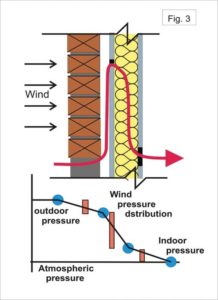
During the 1980s and 1990s building owners faced severe building envelope problems with rainwater penetration, in-wall condensation, and material deterioration. During this period, it was determined a substantial percentage of the problems were caused by humid air leakage through exterior walls and roofs even though builders applied best practices and complied with architectural drawings and specifications.
This recognition that the air barrier component of the air/vapour barrier assembly was required to be structured or structurally supported was recognized by the Institute for Research in Construction (IRC) of the National Research Council Canada (NRC) in 1981 and introduced in the 1985 NBCC.
The material suppliers caught on quickly, but the development and innovations were focused on air leakage reduction without much recognition that air leakage is pressure driven and a pressure difference is a physical load to be considered in the air barrier system design. Designers, architects, and engineers did not respond until later years, and still without any significant structural consideration.
Air pressure difference was examined as a structural load in an early IRC/NRC research project. One such project involved a laboratory experiment of a full-scale wood-frame wall covered in polyethylene film and exposed to an increasing air pressure difference (Figure 2, page 28). The findings were interesting and disappointing. In this experiment the polyethylene film eventually failed to contain an adequate air pressure load. The polyethylene film eventually failed by bulging out between studs, tearing at fasteners, slipping at joints, and deflecting excessively. The theory the polyethylene sheet vapour retarder would perform as an air barrier was not realized. On its own, it would not support an air pressure load from a strong wind event. It failed structurally.
Roof systems are subject to similar considerations. Most wood-frame buildings in Canada support a low sloped roof. The wind pressure profile for these roofs (Figure 2) may be positive (blue) on the windward side and negative (red) on the leeward side. It is known high wind speeds can lift a roof off a typical flat roof of a commercial building. However, it can also occur on a wood-frame building with low-slope roof (Figure 2). In commercial buildings, a Factory Mutual, FM I-90 Roof Standard, specifies the roof membrane must not lift from the building at a wind speed of less than 145 km/h (90 mph) (wind uplift pressure 2155 Pa/m2 [45 lb/sf]. This becomes the design wind load for the structural air barrier system of a roof system.
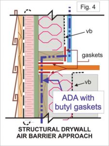
A structural air barrier system
In building science and technology, it is expected the building envelope and its components will perform their functions for the life of the building. For example, insulation will retard heat flow for a long time; the cladding will control rain penetration for years; the vapour barrier will limit water vapour diffusion (water molecules passing through a material) through wall and roof assemblies; and the air barrier will contain the air of a building and prevent outdoor air from infiltrating into the building interior or out as moist exfiltration air, and support the air pressure differences applied without fail for the life of the building.
At this time, it is believed most designated air barrier systems do not perform their function for long. They fail structurally at connections and attachments. Investigation of problem building envelopes (by the author for 35 years) has found designated air barrier systems of most buildings examined were inadequate to support the wind loads and failed in the early life of the building envelope. Once failed, it is not immediately apparent as the air barrier system is generally hidden within the construction. However, it is easily recognized when other symptoms begin to appear. Symptoms such as efflorescence, icicles in winter, spalled masonry, corrosion tracks on the cladding’s surface, flooding in spring, and more.
So, what is an effective and durable structural air barrier assembly? If the air barrier must control air leakage and support air pressure difference for the life of the building, one must examine the attributes of materials assemblies that can resist air leakage to a minimum of 0.2 L/s.m2 (0.039 cfm/sf) at a pressure difference of 75 Pa (1.56 lbs) of the system (air impermeability) and provide the necessary functional and durable structural connections, to resist design wind loads and long duration small pressure loads. For discussion purpose of this article, air barriers assemblies are categorized into four groups of components. These include:
• membranes and coatings;
• rigid paneling and solid materials;
• joints and connections; and
• cladding systems.
Membranes and coatings
Membranes and coatings for air barrier construction are selected because of their air impermeability (low porosity) properties. They resist the passage of air through the material. They are flexible, easy to install, and supplied in roll form, paste, or liquid. However, by themselves they are not suitable as standalone air barrier systems. The normal air pressure loads during the life of the building will displace, tear apart, un-bond, deflect excessively, and destroy the barrier’s continuity without the necessary structural support and connections. Membranes and coatings include aluminum foil, polyethylene film, building papers, elastomeric roof, wall membranes, and more.

