The challenges with epoxy-set anchors
Limestone cornice
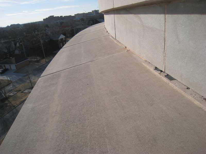
A four-storey office building was constructed in 2003 to provide additional space needs for a facility constructed in 1936 in central United States. The structural system for each building consists of reinforced concrete and is clad with Indiana limestone. The building structure for the 2003 addition was a combination of cast-in-place reinforced concrete and concrete masonry unit (CMU). An air space of 75 mm (3 in.) was between the limestone and backup and an exterior limestone cornice is located near the top of the exterior wall above the fourth floor.
The limestone cornice units are nominally 1110 mm (44 in.) wide x 1000 mm (40 in.) high and the cornice projects out approximately 690 mm (27 in.) from the face of the building. The bottom half of the cornice has a concave profile and is nominally 203-mm thick at the bottom edge of the unit (Figure 7).
Each limestone cornice unit is supported by a pair of 250-mm (10-in.) long galvanized steel angles—the centre of each angle aligns with the head joint between adjacent units and each cornice is rabbeted to allow the cornice to be seated on the angle. Each angle has a stainless steel bar shop welded to its toes. Lateral support along the top edge of each unit is provided with two 8-mm (3/16-in.) thick stainless steel straps, each located approximately 300 mm (12 in.) from the end of each unit. Each strap is nominally 75 mm wide and the downturned portion of the strap is embedded into a kerf in the top face of the limestone cornice, approximately 25 mm (1 in.). Each strap is anchored through the face of a concrete spandrel beam with a 13-mm (1/2-in.) diameter stainless steel expansion anchor. Each limestone cornice unit was estimated to weigh more than 900 kg (2000 lb) and was reported to have been installed using a crane. A schematic cross-section of the detail is shown in Figure 8.
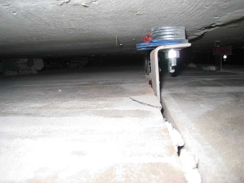
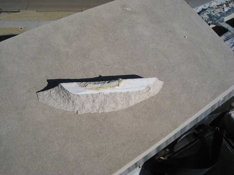
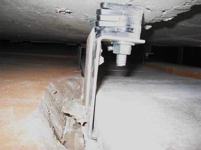
In response to reports of mortar bond separation and outward displacement of isolated cornice units, an investigation was performed in 2008 to identify the potential cause(s) of distress. A visual survey of all cornice units indicated cracked and/or bond separation of mortar occurred at approximately 30 per cent of all mortar joints between adjacent cornice units. In a few instances, mortar had become dislodged between the top horizontal surface of the limestone cornice and the limestone ashlar directly above it (Figure 9). Inspection openings were made by removing the limestone cap at the top of the exterior wall, cutting through a membrane flashing, and examining the back face of the cornice. The inspection opening allowed examination of two cornice units and four strap anchor connections. Spalls were observed to the back face of the limestone cornice at each strap anchor connection (Figure 10). In some cases, epoxy remnants remained bonded to the limestone face of the kerf slot at the limestone spalls (Figure 11), and in other instances, remaining epoxy remnants bonded to the strap anchor (Figure 12). Analysis of the strap anchor connection revealed the limestone at the kerf has sufficient strength to resist design loads.
It is unknown if the anchor voids were specified to be filled with mortar or sealant. However, the cornice anchors were likely set with epoxy to increase the installation rate of the limestone cornice units.
Conclusion
In its fully cured state, epoxy is typically a hard material with a modulus of elasticity comparable to that of limestone. Therefore, when the temperature is elevated relative to when the epoxy cured, thermal expansion of epoxy occurs that is significantly greater than of the adjacent limestone. Where the epoxy is confined by the limestone within dowel holes or kerfs, significant expansive forces can develop that, to an extent, are resisted by the adjacent limestone. With an increase in temperature and resulting epoxy expansion, the limestone is no longer able to accommodate the developing expansive forces depending on the geometry of assembly, most importantly edge distance and void volume. The expansive forces can be significantly high, resulting in shear and/or tensile stresses in the limestone exceeding the ultimate strength of the material. The cracking and spalls observed in the case studies presented are consistent with the development of high stresses at dowel and kerf connections the author has observed on other buildings and during controlled laboratory testing.
The confinement of epoxy within anchored limestone assemblies can lead to cracking in different types of assemblies. Additional analytical and laboratory studies are needed to further evaluate the mechanism(s) causing cracking for epoxy-set anchors in limestone and other materials.
Consistent with the Indiana Limestone Institute of America (ILI) recommendations, anchor voids in exterior limestone should be filled with mortar or sealant, or other non-expansive, stable material. Filling anchor voids in dowel holes or kerfs with epoxy should only be considered after careful study of all material properties and anchorage geometries proposed for use as part of a limestone attachment assembly.
 Steven G. Naggatz, AIA, NCARB, investigates and designs repairs for distress conditions in existing buildings. Steven’s expertise lies in exterior wall systems with a focus on structural adequacy, corrosion, anchorage devices, water infiltration, and durability. Naggatz has authored papers on exterior dimension stone cladding and paving systems and has presented other papers on façade repair and rehabilitation design. He can be reached at snaggatz@wje.com.
Sign up for our weekly newsletter
Construction Canada weekly newsletters give the latest AEC industry news for those who build, design, engineer, specify, renovate or operate in the built environment.
Products & Services


Read the Latest Issue