The challenges with epoxy-set anchors
Case studies
Considering the rapid set and connection strength of epoxy-set anchors, there has been an increasing prevalence to anchor dimension stone panels on exterior façades where the anchor void is filled with epoxy. Based on available data, the co-efficient of thermal expansion of epoxies used in construction can be between 10 and 30 times higher than the co-efficient of thermal expansion for limestone. Considering the potential for development of cracks or spalls resulting from the inherent material property differences, the use of epoxy to fill anchor voids in limestone attachments should be carefully evaluated prior to specifying its use as part of an attachment system. The following case studies present circumstances in which the variables in epoxy-set attachments were likely not considered prior to installation.
Limestone balustrade
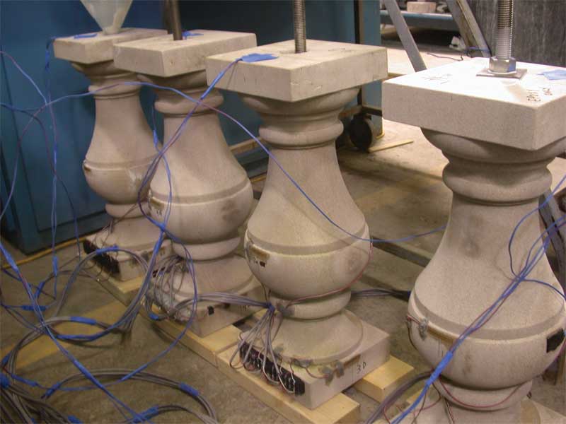
Plans for reconstruction of an aging urban roadway called for the removal and replacement of a limestone balustrade that separated street-level pedestrian sidewalks from a river-level promenade below. The balustrades were built with a combination of traditional elements including bottom and top rails, intermediate piers, and balusters, all constructed of Indiana limestone (Figure 1). The balustrade was built over a period of approximately nine months, between June 2002 and February 2003. Vertical cracks were observed in the balusters within a few months after project completion.
Each baluster has an hourglass profile—plan dimensions at the top and bottom are approximately 200 mm (8 in.) square and each unit is 0.6 m (2 ft) tall. The widest point near the mid-height of the unit is 200 mm and the narrowest point is 90 mm (3 ½ in.). Each baluster was fabricated with a 40-mm (1 ½-in.) continuous vertical hole to accommodate a 20-mm (¾-in.) diameter stainless steel threaded rod that, in turn, is anchored into the supporting concrete structure. The annular space between the threaded rod and baluster hole was reportedly filled with an epoxy grout. A washer and bolt on top of the baluster secured it in place.
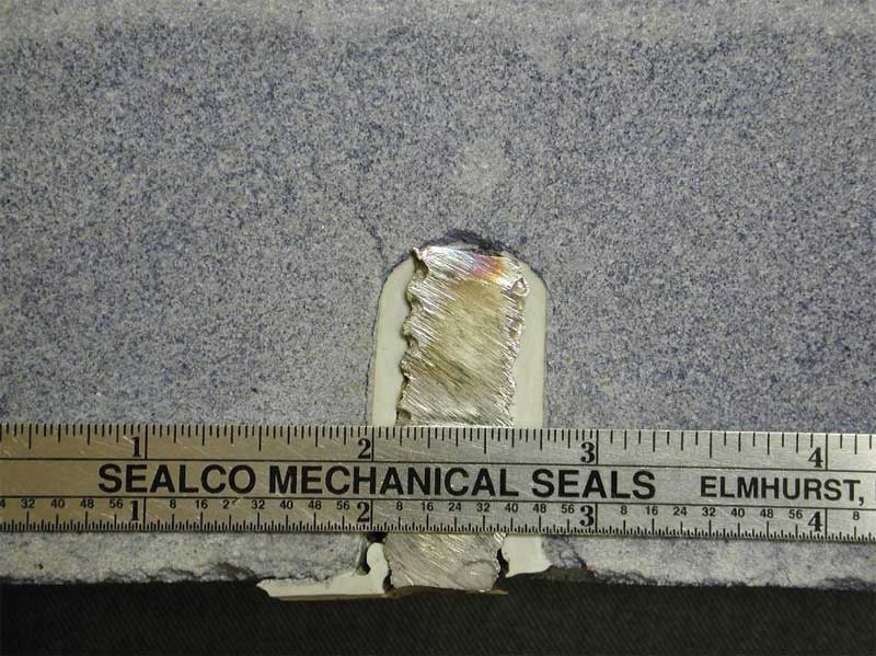
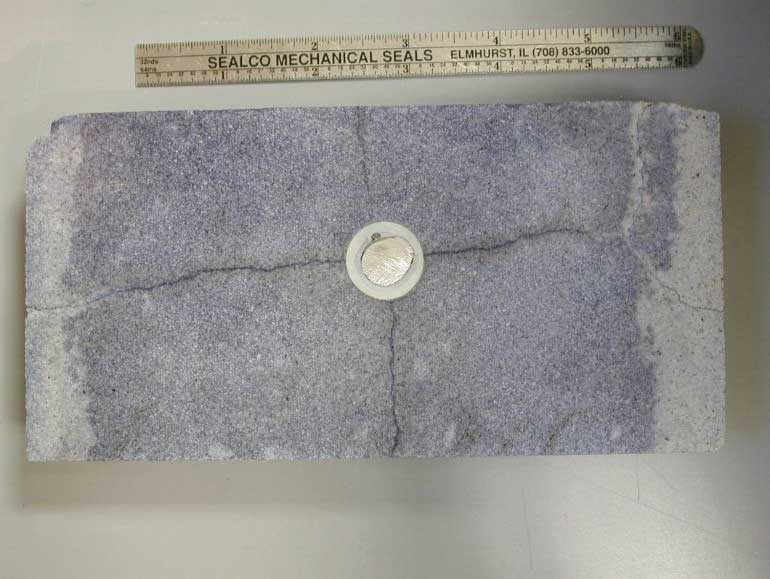
Close-up examination of distress (Figure 2) revealed the cracks are wide (between 0.5 and 0.9 mm [20 and 35 mils]) near the base (Figure 3) and the middle of each baluster cracks range between 0.18 and 0.9 mm (7 and 20 mils) near the top. The bolts on top of the baluster were found to be only hand tightened, and therefore, likely induced very little stress while tightening the bolts and provided minimal restraint in service. Destructive removal of representative balusters revealed at least two different types of materials were used to fill the annular space between the inner walls of the hole and the threaded rod. Testing of the epoxy and epoxy grout that were reportedly used to set the balusters show that the co-efficient of thermal expansion vary between 6.67E-05 (epoxy) and 2.88E-05 (epoxy grout) (Refer to ASTM C531, Standard Test Method for Linear Shrinkage and Coefficient of Thermal Expansion of Chemical-resistant Mortars, Grouts, Monolithic Surfacings, and Polymer Concretes).
The 100 per cent epoxy has a co-efficient of thermal expansion approximately 22 to 28 times the co-efficient of thermal expansion of limestone (estimated to be 2.4E-6 to 3.0E-6 in/in/F).
Four limestone baluster specimens and attachments were constructed in a laboratory to replicate the as-installed assemblies and were subjected to thermal cycling in an attempt to simulate exposure of service conditions (Figure 4). Two specimen balusters were constructed using epoxy and another two with epoxy grout. During the construction of the mockups, it was difficult to install the epoxy grout, as it was very thick and had to be placed in layers into the annular void space. Further, the epoxy grout had to be rodded in order to promote consolidation. The 100 per cent epoxy was easily poured into the holes. It is reasonable to assume the epoxy grout would be very difficult to place under field conditions, especially in cold weather.
Each baluster was instrumented with four stain gauges and two thermocouples. Two strain gauges were attached in the middle of each baluster (at the belled-out section) at opposing edges of the hole. Two additional gauges were installed at the base of each baluster, also at opposing edges of the hole, and rotated 90 degrees with respect to gauges at the middle of the baluster. Thermocouples were installed at the top and bottom of each baluster. The balusters were cycled between 2 and 32 C (35 and 90 F) for seven cycles, and the hot and cold temperatures were each maintained for 12 hours. The balusters were then cycled between 2 and 43 C (35 and 110 F) for 12 cycles, held at the cool temperature for 12 hours, and for 24 hours at the high temperature. A data acquisition system recorded the temperature and strain readings every 15 minutes.

Readings obtained from the strain gauge at the bottom of the 100 per cent epoxy specimens demonstrated a ‘ratcheting’ effect, whereby the epoxy gains tensile strain without full release of the strain. The testing was performed on behalf of a private entity, and at their request, the thermal cycling was terminated after 20 rounds, at which point no visible cracks occurred in the test specimens. However, it is possible that with further cycling, cracks may have developed in the limestone due to tensile fatigue. Stresses could be aggravated by non-uniform expansion of the epoxy relative to the limestone during periods of increasing temperature. As the balusters heat up, the epoxy expands more than the limestone and the former can create a hoop stress in the balusters consistent with cracking observed during inspection of field conditions.
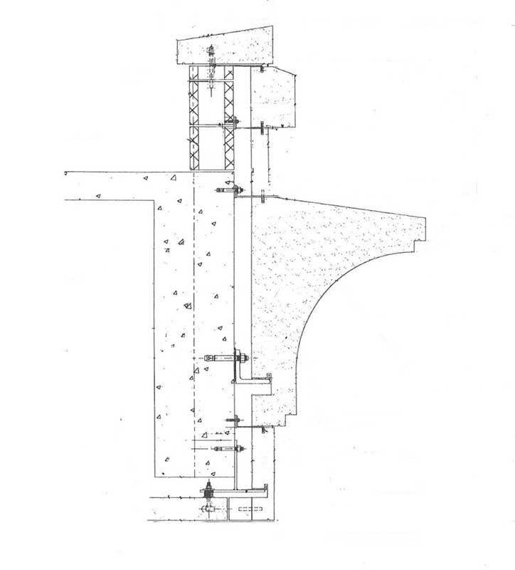
The confinement of epoxy in stainless steel dowel attachments has led to the development of similar types of cracking in cast stone balustrade elements on other projects including dowels installed between balusters and a top rail (Figure 5) and between adjacent top rail sections (Figure 6).
Sign up for our weekly newsletter
Construction Canada weekly newsletters give the latest AEC industry news for those who build, design, engineer, specify, renovate or operate in the built environment.
Products & Services


Read the Latest Issue