Reviewing Raised Floor Standards: Specifications for a growing industry
By Scott Alwine, LEED AP
The desire to improve indoor air quality (IAQ), increase energy efficiency, and reduce carbon footprints is bringing architects and engineers in various business sectors to the table in search of cost-effective solutions to the challenge of going green.
Raised access floors can provide sustainable, high-performance benefits in both new construction and retrofit applications. These assemblies also bring improvements to personal comfort, acoustics, energy efficiency, daylighting, and esthetics, while ensuring reductions in operating costs and downtime associated with technological and workspace organizational changes.
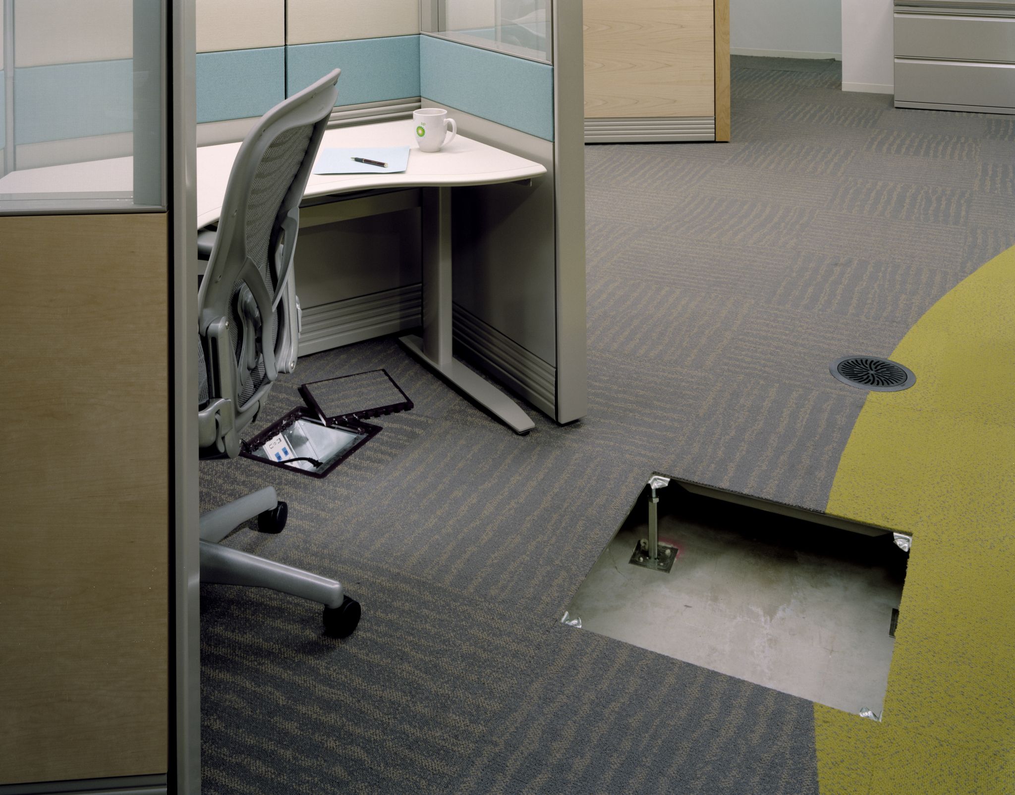
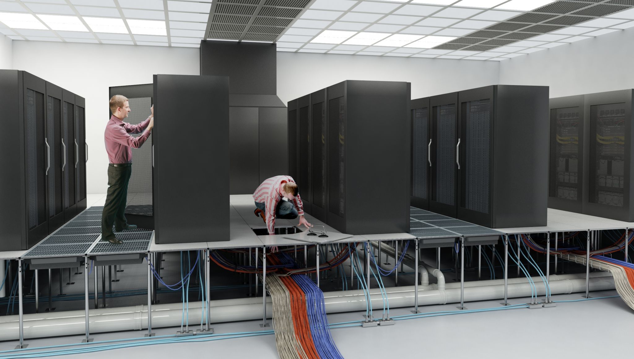
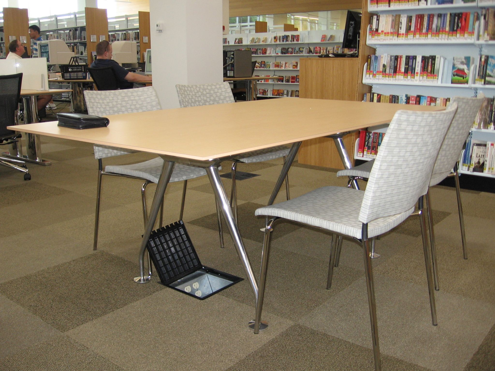
A raised access floor comprises an understructure and welded (in some, but not all areas) steel floor panels filled with lightweight cement. The understructure provides positive positioning (i.e. the pedestal automatically holds the panel in place, keeping it square during installation) and lateral retention, ensuring the floor is soundly supported on all contact points. The square floor panels (e.g. 610 x 610-mm [24 x 24-in.]) use typical finished floor heights from 63.5 (2 ½ in.) to 610 mm on an understructure that also offers a height-adjustment device to ensure the finished floor is level, even when the slab is not.
Under the panels, an underfloor pathway or plenum provides housing for:
- service distribution system;
- modular wiring;
- passive or active zone cabling; and
- HVAC service.
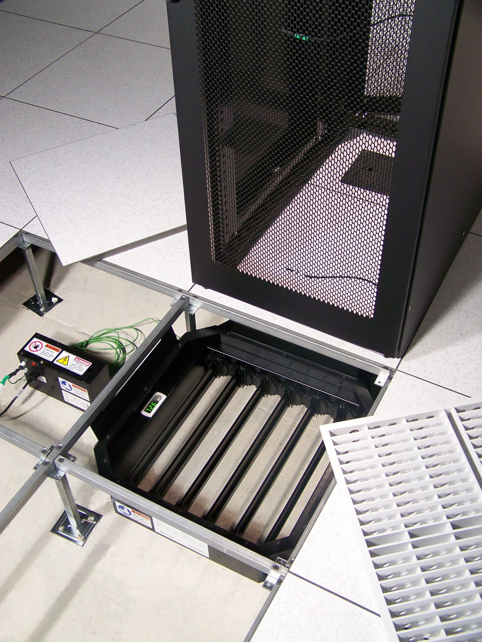
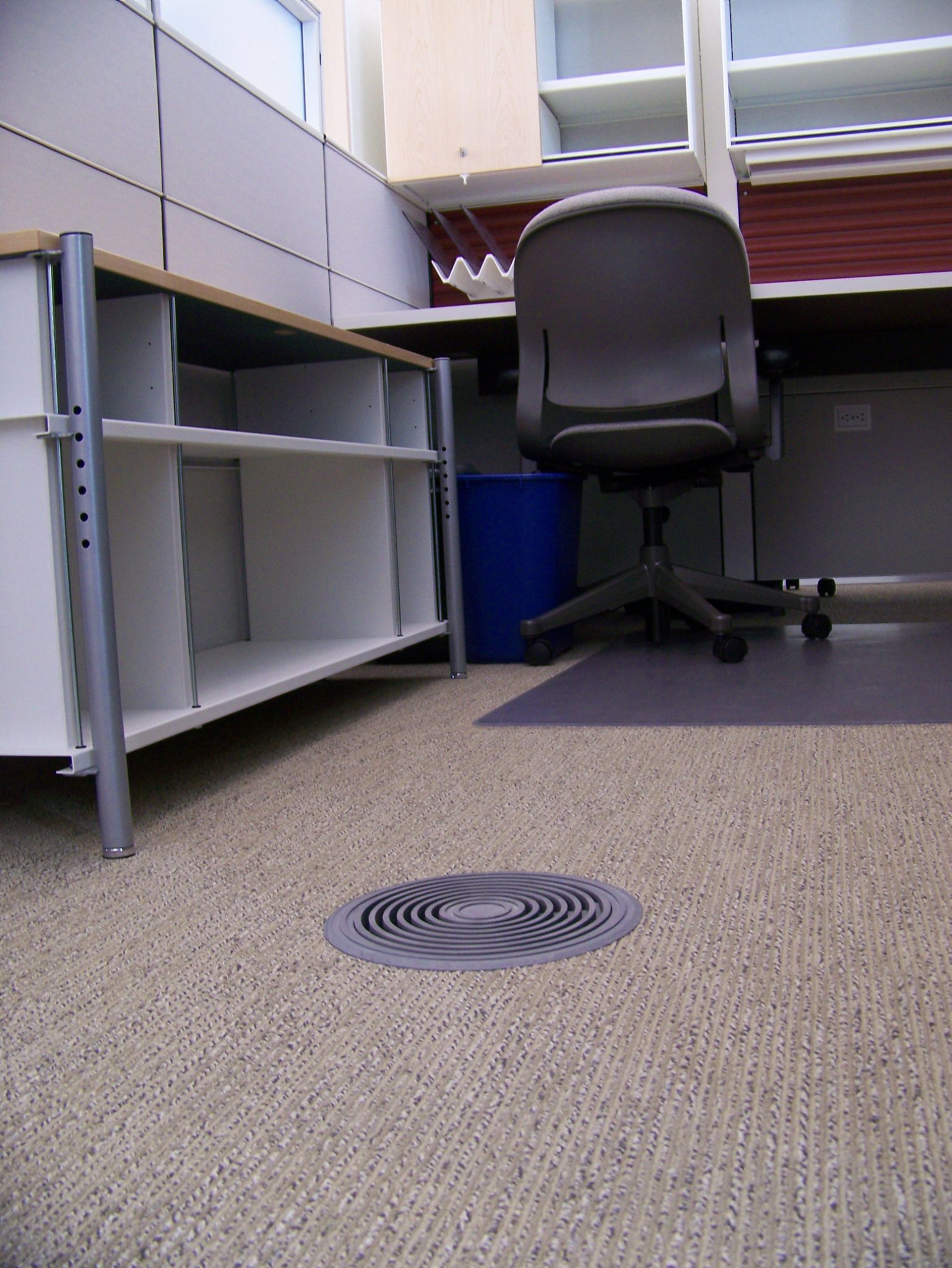
Using the plenum as an underfloor air distribution (UFAD) system eliminates the need for overhead ductwork and dropped ceilings. Instead, air diffusers in the floor deliver conditioned air directly to the occupied zone, typically identified as the space from floor level up to 1.8 m (6 ft). In this process, older, warmer, contaminated air is carried to the ceiling by natural convection and removed through return outlets, keeping it out of the occupied zone. (When there is a drop ceiling, there is usually an overhead return plenum. If there is no drop ceiling, typically return ductwork is installed.) The result is improved indoor air quality.
Since an UFAD system supplies air from the floor without having to pass through the warmer air near the ceiling, air can be delivered at warmer temperatures and lower pressure. The static pressure required in the plenum of a UFAD system is typically 12.5 Pa (0.05-in. wg), which is significantly less than the amount of pressure required to force air through rigid ductwork in an overhead system. As a result, the HVAC uses less fan energy, while the increased supply temperature—typically 18 C (65 F)—can expand the use of ‘economizer modes.’ (This is employed when the outside temperatures and humidity are within an acceptable range, such that the air can be brought directly into the building without additional cooling or dehumidification.) For the building owner, this means a reduction in HVAC energy costs by as much as 20 to 30 per cent.
UFAD can be a key strategy for creating a green building. Over the last several years, this technology has become increasingly popular. Today, approximately 25 per cent of all office buildings in the United States are built with raised floors. This figure is consistent with much of Canada—in cities like Toronto, it is even more prevalent on this side of the border. (In many Asian and European countries, the market share is larger.)
In Canada and the United States, the fact the adoption rate for raised floors has increased during downturns in commercial construction history is no coincidence. The design/construction community is building offices using more flexible and environmentally friendly solutions. Raised floors with underfloor service distribution complement this strategy by helping accommodate unknown future change and reducing the building’s overall carbon footprint.
New technologies improve energy efficiency
These benefits, as well as the previously discussed energy savings, have the potential to increase with the introduction of new UFAD system enhancements, including chilled beam technology and phase change panels. In-floor active chilled beams bring cooled or hot water under the floor to condition the air directly at the building perimeter, where heat loss/gain can significantly impact energy use.
By placing the chilled beam in the floor rather than overhead, primary air from the plenum can be used across a fin tube coil to increase heating and cooling capacity. Conditioning with a perimeter hydronic solution minimizes the air volume required to condition the perimeter and creates the potential to downsize central- or multiple-zoned air-handling units (AHUs) or eliminate fan-powered terminals that supply the perimeter.
In-floor active chilled beams are designed to provide a high-capacity cooling or heating method for an office space’s perimeter, conditioning the façade loading that typically drives a building’s total HVAC requirements. By accomplishing conditioning with a perimeter hydronic, rather than an all-air, solution, the volume of air required to meet the perimeter’s conditioning needs can be minimized while still meeting ventilation requirements.
Minimizing air volume creates the potential to downsize the central- or multiple-zoned air handlers or eliminate fan-powered terminals often used to supply the perimeter zone of a UFAD system. Lower air volumes can also help to lower the finished floor height of the design. Together, they contribute to significant savings of energy and maintenance costs throughout the lifespan of the building. In-floor chilled beams require little to no ductwork, as they use the primary air supply from the UFAD system.
Also new to the industry are panels incorporating advances in phase-change materials (PCMs) to reduce indoor air temperature fluctuations and save energy. As their name suggests, these materials rely on a thermodynamic transition of physical matter from one state to another (e.g. liquid to solid, solid to liquid) due to a change in energy levels. Akin to an ice cube melting to keep a drink cool, PCMs absorb solar and building thermal energy during the normal temperature deviations throughout the day. As the material changes states it absorbs energy allowing for natural safe passive energy savings to occur.
For example, one proprietary system comprises steel-welded shells filled with a mixture of structural cement and microscopic spheres of encapsulated, bio-based PCM that allows the panel to absorb thermal energy. The spheres maintain their size, shape, and integrity throughout phase transitions, allowing the panels to integrate into a raised floor installation providing a low-impact thermal mass to absorb energy during the day that would otherwise affect both the energy efficiency and comfort level of the office. The stored energy is then released again overnight as the temperature drops below the 24-C (75-F) melting point.
Such panels would be installed at the building perimeter; during daytime peak solar loads, the material embedded within a welded steel panel melts, absorbing energy that would otherwise be radiated back into the room as heat or transferred to the airstream. This stored energy is held within the panel until colder air during nighttime off-hours, which allows the phase-change material to re-solidify and release absorbed heat back into the space, producing a more stable and comfortable environment during the day, while decreasing demands on HVAC systems and reducing energy costs.
Understand performance when specifying raised floors
Almost all Canadian commercial buildings (i.e. not data centres) use either a 1000 or 1250-lb concentrated load rating. However, some buildings require different loads based on the use in some areas. It is common to see heavier panels used in service corridors or areas with high ceilings where scissor jacks maintain lights and other ceiling features.
To appropriately specify raised floors, it is important to determine how they will be used in a building. Understanding load performance is critical. The raised floor system is made up of a panel and supporting understructure. These components give the system a specific set of load performance characteristics. Various panel and understructure options can be used to meet a building’s specific requirements, including light industrial use and seismic zone requirements.
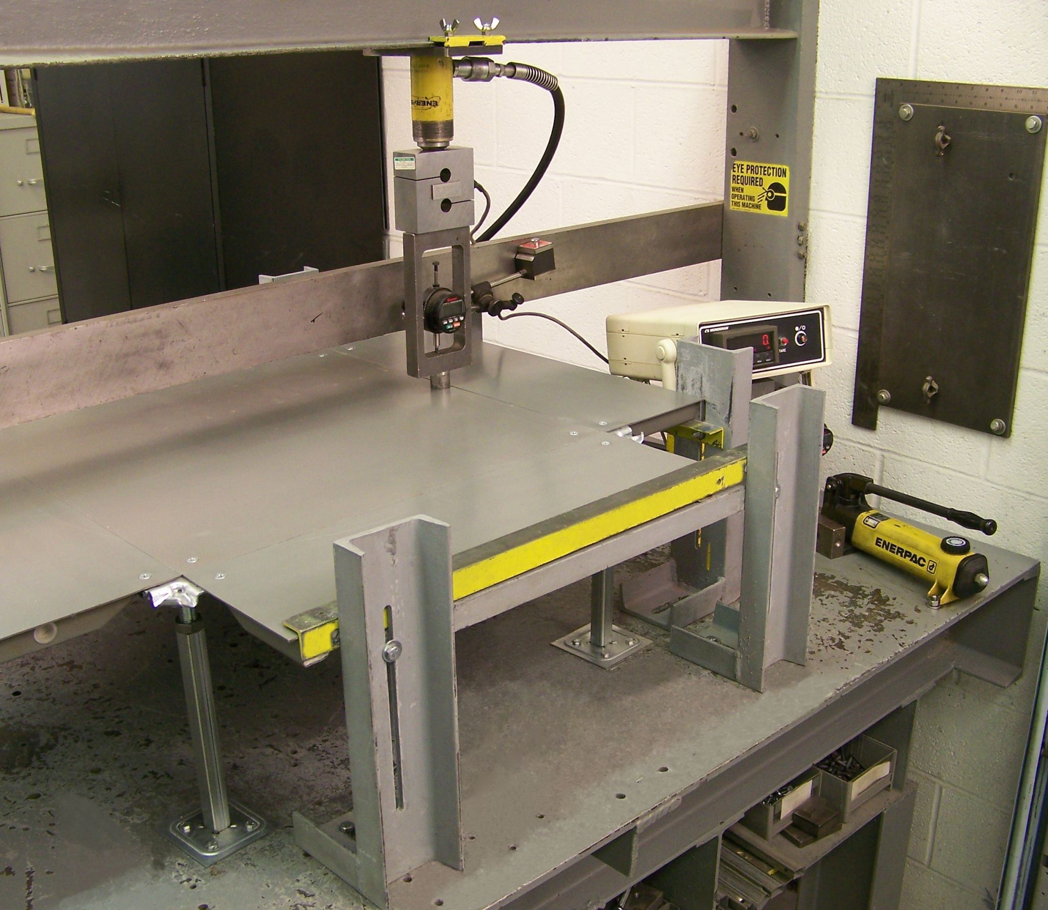
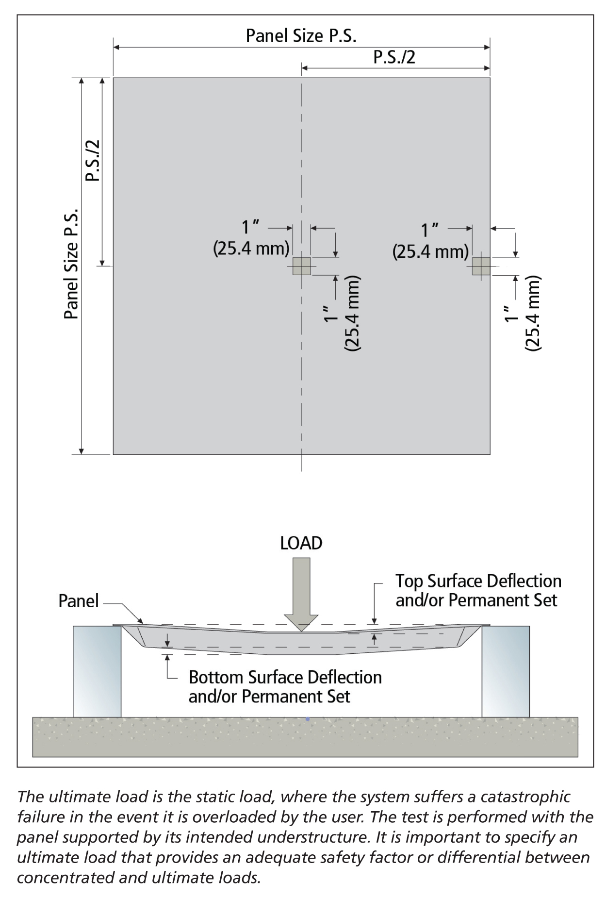
Several common load performance criteria are used to specify a raised floor system. Static point loads, such as concentrated and design loads, are applied to the raised floor panel in a testing lab using a 645-mm2 (1-si) square indenter. The indenter simulates the load applied to the system where desks, other furnishings, and equipment sit on the floor. The ultimate load is the static load limit, which is a theoretical simulation of a catastrophic failure in the event it is overloaded by the user. The safety factor is the ultimate load divided by the concentrated load.
Dynamic loads, such as rolling and impact loads, specify a system’s ability to handle objects being moved over the floor. These loads typically take place during the initial move-in or during office renovations, but special consideration should be given to areas experiencing routine rolling loads, such as service corridors and lobbies. In these areas, a heavy-duty raised floor may need to be specified.
The good news is raised floor systems are interchangeable, so stronger panels can be used only where needed and the remaining building can be specified with a lighter panel grade. Rolling loads are typically performed in a 10 or 10,000 pass test, in which a raised floor system is required to support a specific load rolled over it a specified number of times without experiencing failure. Impact load is often specified to ensure the panel can withstand a heavy object being dropped on it without catastrophic failure. These tests are a combination of Ceilings and Interior Systems Construction Association (CISCA) methods and common structural engineering techniques.
Dust under the floor is not typically an issue, provided the underfloor plenum is kept clean during the construction of the building. Once the building is turned over and operational, the air is filtered the same way it is with traditional overhead system. Large spills could require the removal of some panels and cleaning of the underfloor area. The good news is the panels are designed for easy removal and this cleanup can be handled quickly.
Specifying UFAD
UFAD is helping increase use of raised floors. However, plenum integrity is a critical, but oft-missed, aspect of the specification of these systems. It is vital the entire design/construction team does its part to ensure the underfloor plenum is properly sealed. This process starts with providing specifications and details for constructing a well-sealed, solid plenum. All contractors working in the plenum space needs to be aware of their responsibilities and should be equipped with the information needed to successfully complete their work.
Taking this holistic approach to design and construction may require regular meetings with key individuals on the construction team throughout the entire design process. It is a good idea to specify these meetings and other strategies, using the six-step process that follows, to ensure good plenum integrity.
1. Design
Specifications and performance requirements that create awareness and responsibility for plenum-sealing integrity should be included in all divisions of the specifications. Drawings detailing the construction requirements for the UFAD plenum should also be provided.
2. Pre-bid meeting
A pre-bid meeting should be held in order to inform all subcontractors of the plenum-sealing and mockup construction requirements.
3. Pre-construction
Pre-construction meetings should also be specified to reaffirm the plenum-sealing requirements to each subcontractor division.
4. Mockup
The construction and testing of a mockup needs to be specified; it has to include all actual building conditions relative to the UFAD system.
5. Quality inspections
One must specify use of a commissioning agent to audit the construction process, perform air leakage testing on the mockup and final installation, and provide detailed reporting to the general contractor that ensures the construction of the UFAD system follows the specified requirements.
6. Air leakage requirements
There are two basic categories of UFAD air leakage:
- Category 1 leakage occurs outside the intended occupied zone; and
- Category 2 occurs when plenum air leaks into the occupied zone through spaces other than the designed air distribution devices, such as diffusers.
Category 2 leakage is unique to UFAD systems because all this leakage goes into the occupied space. In a traditional ducted overhead system, there can only be Category 1 leakage, as all leakage and short-circuited air enters the return plenum and does not reach the intended zone.
Total air leakage from the plenum should not exceed 10 per cent of the design airflow for Category 1 leakage and 10 per cent of the design airflow for Category 2 leakage, when tested at the typical static pressure range of 12.5 to 25 Pa (0.05 to 0.10 in. w.g. max).
The allowable Category 1 leakage number used to commission UFAD systems is higher than overhead distribution. This number is used because the entire HVAC system, from supply point to diffuser, is being tested in a UFAD assembly. By comparison, overhead systems typically only test the trunk or high and medium pressure ducts. The test being performed on a UFAD system is the equivalent to using the following equation on an overhead system:
Leakage = supply duct + variable air volume (VAV) box + low-pressure duct + flex duct + diffuser & flex connection
Conclusion
Good plenum integrity is critical to a successful UFAD design, and proper specification is necessary to ensure the system performs as intended. As a result, many raised floor manufacturers offer plenum-sealing support and presentations, as well as details and specification language to assist in the creation of construction documentation for an airtight plenum.
To ensure the successful long-term operation of a building with a raised floor system, it is critical to provide clear specifications for plenum-sealing and all load performance requirements, including static loads, dynamic loads, and safety factors.
Construction documentation is also important to project success. Manufacturers can provide assistance in writing specifications and detailing so building owners end up with a UFAD system that improves building efficiency and IAQ, enhances daylighting and esthetics, assists in occupant comfort, supports flexibility, and contributes to sustainability goals.
 Scott Alwine, LEED AP, is a marketing manager with Tate Inc. He has more than 10 years of experience in the building products and services industry. Alwine holds a bachelor of science in manufacturing technology and a master of science in business administration from California University of Pennsylvania. He is a member of the Commercial Real Estate Development Association (NAIOP) and the Building Owners and Managers Association International (BOMA). Alwine can be contacted at salwine@tateinc.com.
Sign up for our weekly newsletter
Construction Canada weekly newsletters give the latest AEC industry news for those who build, design, engineer, specify, renovate or operate in the built environment.
Products & Services


Read the Latest Issue