Polished concrete: Closing the expectation gap
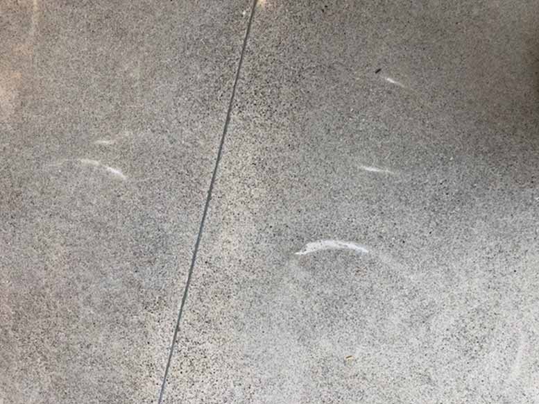
Aggregate exposure
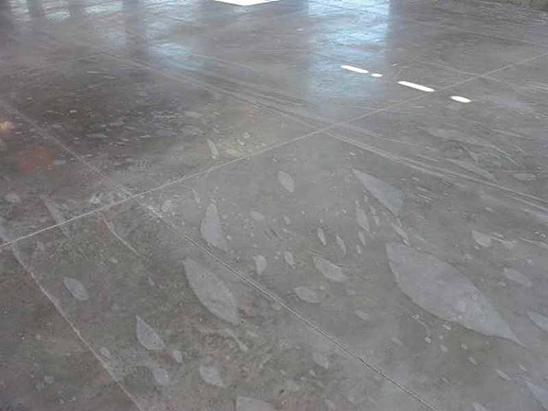
Photo courtesy Chris Sullivan Chem systems
Problems can occur on polishing projects with a specified or desired amount of aggregate exposure. A lumpy floor slab without a good flatness tolerance can result in inconsistency in this area after the polishing process. This situation presents as either too much aggregate exposure (larger stones) or too little (pockets of cream [i.e. areas only containing cement paste and very fine sand particles]).
It should be noted aggregate exposure in concrete polishing will always have some variability. However, high degrees of exposure inconsistency are not esthetically appealing and can be a major source of contention when the polishing work is complete.
The root causes of aggregate exposure issues are mainly related to slab placement or finishing and include low floor flatness (FF), curled joints, inconsistent placement leading to aggregate stacking, and issues with screeding.
FF tolerances impact the esthetics of polished concrete floors. They should be measured in accordance with ASTM E1155, Standard Test Method for Determining FF Floor Flatness and FL Floor Levelness Numbers. One should specify FF 50 or above when laser screed or other tools and techniques are available for pours larger than 1858 m2 (20,000 sf). An FF of 35 should be specified for retail or light commercial applications, grocery stores with drains and penetrations, or buildings with multiple small pours (Read “Specifying The Concrete Slab” by Todd Scharich, Chad Gill, PE, Steve Lloyd, Pat Harrison, and Bruce Suprenant, PE, PhD, FACI, published in the August 2016 issue of The Construction Specifier.).
In addition to calling out FF numbers, the specification can also outline areas of concrete placement that will improve the consistency of aggregate exposure.
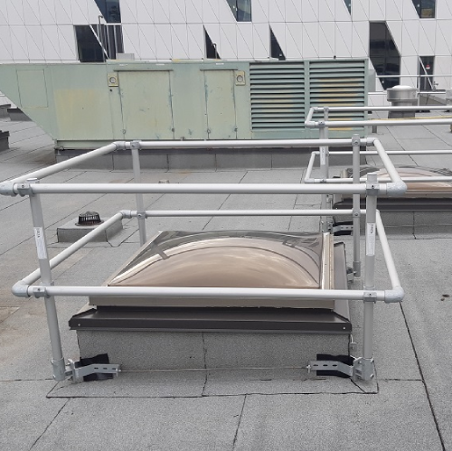
Conditions
Photos courtesy BNE Contractors
Provisions should be made to ensure placement of an architectural floor slab does not interfere with a successful install. For example, it is advisable to outline the requirement to call off a pour if conditions are too cold, wet, or hot or if the building envelope is insufficiently sealed.
Placement
It is recommended to deposit concrete in a continuous operation. This approach does not result in coarse aggregate segregation. Whether placing by chute, buggy, or pump, the key is to be aware consistent and continuous delivery provides the best slab consistency.
Screeding
It is recommended to screed slab surfaces with a vibratory straightedge and strike off to correct elevations. Sufficient paste is necessary at the surface for polishing, which is best accomplished by using a hand-held vibratory bullfloat, vibrating screed, truss screed, or laser screed. The vibratory screed must be moved continuously across the slab because too much vibration at one location drives the coarse aggregate deeper into the slab. This results in variations in coarse aggregate exposure after polishing.
Control joints
The maximum contraction joint spacing should not be more than 24 times the slab thickness or 4.5 m (15 ft), whichever is smaller. This limit is set to not only control out-of-joint cracking, but also minimize slab curling. If the slab edges curl, the grinding and polishing will expose more coarse aggregate at the corners. The engineer should determine the maximum contraction joint spacing to minimize both cracking and curling.
Sign up for our weekly newsletter
Construction Canada weekly newsletters give the latest AEC industry news for those who build, design, engineer, specify, renovate or operate in the built environment.
Products & Services


Read the Latest Issue