Plenum barriers, speech privacy, and workplace 2.0 fit-up standards
Plenum barrier materials and installation
Plenum barriers can be constructed of a variety of different lightweight materials, including:
- limp, mass-loaded vinyl (MLV);
- stone wool insulation with a foil facing;
- standard gypsum wallboard; or
- some combination of these materials.
This article omits research done on MLV plenum barriers because they generally do not perform as well as stone wool insulation and gypsum board plenum barriers, and plenum-rated MLV is much more costly than stone wool insulation and gypsum board. Additionally, MLV plenum barriers are more time-consuming to install.
While gypsum board plenum barriers are just as cost-effective as stone wool plenum barriers and work similarly well acoustically, the rigidity of the material can be a disadvantage in some buildings where there is floor/roof deflection, seismic joints, or expansion/contraction joints. Therefore, this article focuses on stone wool plenum barriers due to their low cost, relatively quick installation, pliability, and high sound isolation performance. (It is important to remember there is a very large difference between stone wool ceiling panels and mineral fibre ceiling panels. These are two separate materials with separate properties and performance. All research in this article was conducted with stone wool ceiling panels—readers should not assume the same results will be realized if they use mineral fibre ceiling panels.)
The goals of this most current phase of the Optimized Acoustics Research Program involve testing whether stone wool plenum barriers could:
- achieve the STC/CAC 45 rating required for the enhanced privacy level in Workplace 2.0; and
- be simplified to decrease material cost or installation time.
The test series investigated whether the thickness/weight of the plenum barrier could be decreased, and the foil facing and taping of vertical seams be eliminated.
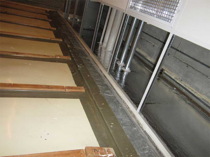
A series of sound isolation tests was performed on a suspended, modular, acoustic ceiling system with and without various lightweight plenum barriers under laboratory conditions in a dual-room chamber. For the baseline test, the specimen comprised a metal tee-bar suspension system filled with 16-mm (5/8-in.) thick stone wool ceiling panels (CACpanel 23), but no plenum barrier above the demising wall. Subsequent tests added various lightweight plenum barriers.
In all cases, the ceiling grid ran continuously (i.e. uninterrupted) over the top of the laboratory’s central demising wall. A senior test engineer performed all tests at NGC Testing Services in Buffalo, NY. The laboratory is accredited by the National Voluntary Laboratory Accreditation Program (Laboratory Code 200291-0). Tests were performed according to ASTM E1414, Standard Test Method for Airborne Sound Attenuation Between Rooms Sharing a Common Ceiling Plenum, and ASTM E413, Classification for Rating Sound Insulation.
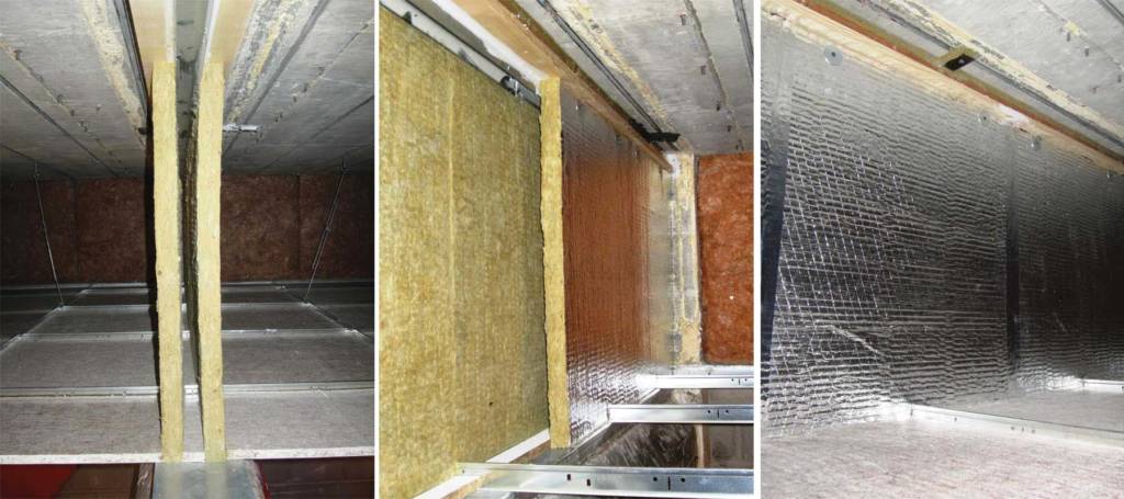
Figure 2 shows a double-layer, stone wool, plenum barrier being installed in the laboratory for testing. The stone wool material was 38 mm (1 ½-in.) thick with a density of 128 kg/m3 (8 pcf) and surface weight of 4.88 kg/m2 (1.5 psf). It is important to specify and obtain “actual” 128-kg/m3 (8-pcf) density material—data sheets for some materials contain “nominal” densities, which can be misleadingly high. (Density can be checked during the submittal review process.)
For most of the tests, the plenum barrier panels had a fibre-reinforced foil facing on one side (Figure 3). The foil was oriented toward the open ceiling plenum, not into the small, interstitial air space between the two layers. The plenum barriers were mechanically fastened along the top edge using common, self-tapping, sheet metal screws with insulation washers into a common 41-mm (1 5/8-in.) wide metal channel attached to the test chamber overhead slab. Screws were spaced approximately 305 to 457 mm (12 to 18 in.) on centre (o.c.). Typically, each 610-mm (24-in.) panel had two screws along the top. This created a 41-mm air space between the two layers of plenum barrier board. The bottoms of the plenum barriers were only friction-fitted against the top track of the demising wall and the suspension system. They were not mechanically fastened, glued, or caulked. No neoprene gaskets, as seen in some project-specific plenum barrier details, were used.
Each panel was abutted to the adjacent panels along the sides with no overlap. For some tests, the vertical seams between adjacent panels were taped using 50-mm (2-in.) wide metal tape for sealing butt-joints. The 610-mm wide panels of each layer were staggered 305 mm so the seams were not aligned. This required a small cut along the bottom of one layer of the plenum barrier panels so they could slide down over the bulb of the suspension system and allow the bottom of the plenum barrier panel to sit on the top track of the demising wall.
No caulk or sealant was used. Small gaps around and between some of the plenum barrier panels were visible, but most were closed during installation due to the stone wool’s pliability. The panels were cut slightly oversized and then compressed vertically and laterally during installation, which helped prevent gaps. It was important the ceiling panels did not extend under the plenum barrier. Installed last, the ceiling panels abutted the bottom edge of the plenum barrier, locking it in place.
Sign up for our weekly newsletter
Construction Canada weekly newsletters give the latest AEC industry news for those who build, design, engineer, specify, renovate or operate in the built environment.
Products & Services


Read the Latest Issue