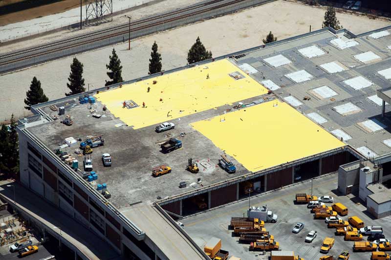
Plaza Deck Restoration: Principles of drainage and waterproofing
Subsurface drainage
The plaza assembly design should enable water infiltrating the wearing surface and system components to be drained at the waterproofing membrane level. Providing membrane-level drainage can prevent premature deterioration of the wearing course and greatly reduce the likelihood of waterproofing and structural deck deterioration.
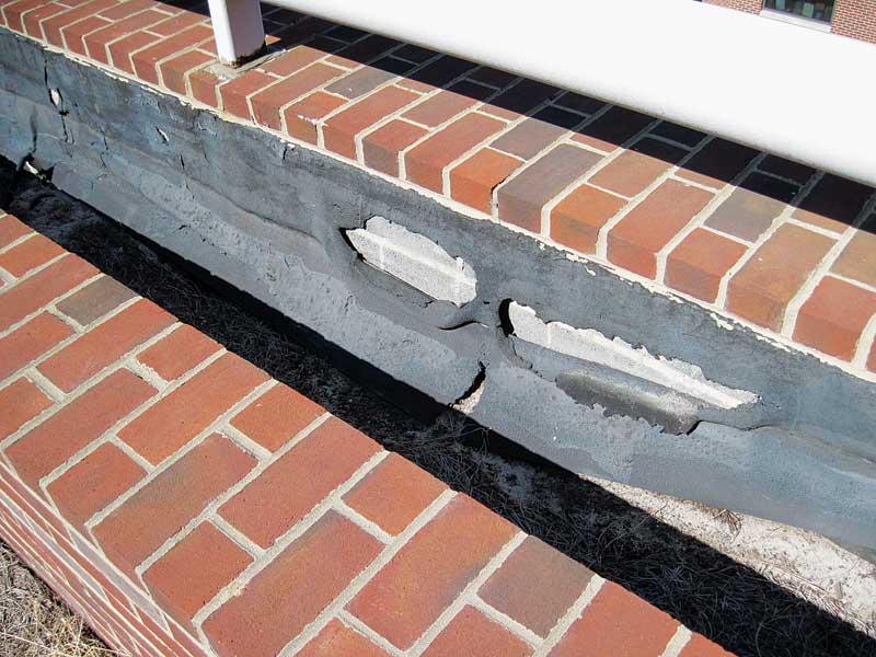
Many older concrete plaza decks were constructed with a level, or near level, deck. Considering normal construction tolerances, deflections in concrete slabs, and normal building settlement, it is not unusual to find certain areas of a structural plaza deck intended to drain do not perform this function. These areas vary in elevation from dead level to very low-slope to positive slope in the wrong direction.
An important factor in the evaluation of the existing conditions is to determine the drainage slope at the surface where the new waterproofing membrane will be installed. A best practice is to provide positive slope-to-drain at the waterproofing membrane level. Generally, the deck slope should be a minimum of 6.4 mm (0.25 in.) over 0.3 m (1 ft) in deck length (an approximate two per cent slope). Since all decks have some unevenness due to construction tolerances and materials, low deck slope will increase the likelihood water will be retained on the membrane. Additionally, the slope should take into account the deck will experience deflection when loaded. The structural engineer can estimate the deflection of the plaza deck to be incorporated in the slope design.
An inverted pyramid pattern providing a four-way slope to an interior deck drain is an efficient subsurface slope layout. Even with proper slope-to-drain, it is advisable to provide a further recessed area (i.e. a drain pan) directly around the deck drain. This is to accommodate the buildup of waterproofing materials at the drain ring so it does not restrict the water flow into the drain.
One should co-ordinate the slope and drain positions with planters, curb walls, and other building elements that could interfere with drainage. Locating internal plaza drains near the mid-span between support columns can help account for load deflection. If a drain cannot be located at the centre of each span, one should consider providing greater slope-to-drain. One critical design element is to slope the deck in a manner that does not cause it to drain across an expansion joint. A best practice is to actually construct the expansion joints in an elevated curb to limit the opportunity for water to flow across the joint.
Restoration of an existing plaza with little or no slope may require adding a tapered layer of concrete over the existing concrete deck––before the waterproofing––to improve drainage. The structural deck-loading capacity and the height of perimeter conditions (i.e. doors and flashings) may limit improvements to the existing slope. When adding a tapered topping slab, a structural engineer must confirm the existing structure can safely support the tapered concrete’s additional weight. It is also good practice to co-ordinate slope on the wearing surface with the slope on the membrane level, and with drains spaced to accommodate desired drainage. To assist with this process, elevation measurements using conventional surveying tools can yield relatively accurate contour results of the structural slab and surrounding elements.
Once the existing elevations and drainage slopes are determined, the designer can assess the need for improving the drainage slope and specify methods to improve it. However, providing a 6.4-mm per 0.3-m drainage slope to an old plaza deck is not generally practical since the existing building elements such as doors and curbs were built in relation to the surface of the existing plaza finishes. Thus, providing a 6.4-mm per 0.3-m drainage slope may require the existing building elements be altered.
In lieu of concrete, tapered rigid insulation has been used on projects when additional load capacity is restricted. This option limits the choice of waterproofing membranes because the insulation is installed first and may change the condensation potential in the plaza deck assembly. Another option is to provide additional drains in the plaza. While this may appear to be a simple solution, adding drains to occupied structures is not always practical.
Prefabricated drainage composites
On decks with a continuous concrete or paving surface for traffic-bearing properties, a prefabricated drainage composite placed over the waterproofing membrane can provide both drainage and uniform support for the assembly.
Drainage composites consist of plastic formed into a 3-D dimpled sheet or geonet cross-grid. The composites maintain a path for drainage between the dimples or cross-grid while supporting overlying materials. Drainage cores are more easily clogged than a paver-on-pedestal system because the drainage area is generally thinner. Soil, concrete, or mortar placed over them can run or be washed into the drain core where the filter fabric is not properly installed. Designs using a drainage composite course should consider the following:
- flow capacity;
- compressive strength;
- filter fabric; and
- thickness of the wearing course to distribute the expected loads.
One should co-ordinate the use of drainage composite with support requirements for the paving system––both during installation and in-service. Drainage composites are available with overall compressive strengths high enough for most applications. The design should also include not installing the paver pedestal directly to the drainage composite. General composite plastic drainage cores have high compression strength when dead loads are distributed through a thick, uniform material layer. However, they are not as good when the load is applied directly at a point to the drainage core.
A drain composite with capacity exceeding the expected flow rate should be selected. For continuous paving systems where most of the water drains off the exposed surface, the expected flow rate at the membrane level is low. However, since access is limited or not an option, thicker drainage cores with higher drainage capacity are still preferred because the larger drainage space is less susceptible to clogging. Continuity of the drainage pathway is imperative––the drainage core should extend all the way to the drain.
Most drainage composite is approximately 6.4 to 11.4 mm (0.25 to 0.45 in.) thick with published flow rates of 10 to 25 Lpm per metre width (9 to 22 gpm per foot width). This test is typically reported for a hydraulic gradient of 1.0 under a pressure load of 172 kPa (3600 psf). For specific product properties, one should refer to current manufacturers’ published literature. Geonet versions have a very low profile and, as such, have a thinner area to transport water and generally have a lower flow capacity than dimple-formed prefabricated drainage cores.
Another item one should consider when selecting a prefabricated drainage composite is the type and properties of the filter fabric bonded to the core. The filter fabric for plaza decks with concrete slabs is generally a woven polypropylene geotextile with high tensile strength properties. In planters, the filter fabric is generally a thick nonwoven geotextile for better filter properties of soil particles. However, no matter which filter fabric is specified, careful installation is needed to prevent debris from washing through the fabric at joints, core edges, or terminations and potentially clogging the drainage composite. For example, a paver bed should not consist of extremely fine granite dust or sand able to migrate through the filter fabric.
Compressive strength is another important design consideration with prefabricated drainage composites. As with flow capacity, one should choose the composite with a compressive strength that exceeds the loads expected. Additionally, the thickness and type of wearing course material is also a consideration with regard to load capacity because the load is disbursed over a greater area with a thicker wearing course than a thin-wearing course. Assembly thickness is extremely important to consider when designing a plaza with pavers laid into a sand or gravel bed. Thin-wearing course coverage can point-load the composite and may cause it to collapse, making the pavers shift and further displacing the sand bed.
Gravel or sand can be used as a drainage layer in plaza paving systems, but this is generally less desirable than either pedestal systems or prefabricated drainage composites because gravel or sand can have lower drainage capacity and adds more weight to the structure. With sand, one should confirm the filter fabric of the drainage composite is suitable with the sand’s particle size.
Drain outlets
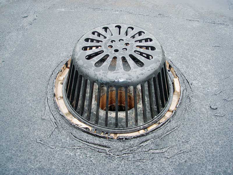
Drains at low points of the waterproofing membrane are needed to receive and carry away water that collects in the drainage layer; these are in addition to the drains at the paving’s surface. Drainage at both levels can be achieved via two-tier drains or by separate systems of surface and subsurface drains. In some cases, water on the membrane level drainage can be drained off the deck’s edge, but this may expose the wall to additional water and potential leakage.
Many two-tiered plaza drains have only a small number of weep openings to collect water on the membrane level. These are prone to clogging with debris or minerals that seep out of the paving and cannot be relied on to provide membrane-level drainage over the long term without maintenance. One should use drains containing large weep openings, providing easy access for clean out wherever possible in the design.
Waterproofing selection
With plaza deck restoration, selecting a waterproofing membrane deserves a thorough evaluation and review process. The designer has a responsibility to specify materials appropriate for the intended application and construction site conditions. The waterproofing system design should be adequately depicted through the details and installation described through the specification. Before selecting the proper waterproofing system, it is also a good practice for one to discuss and fully define all of the performance expectations with the owner.
An important factor in selecting a membrane is the installation’s ‘practicality,’ both as a product and with regard to the site conditions. For example, cold-applied fluid membranes typically require longer curing times and are more susceptible to problems associated with moisture release from the concrete substrate. If the construction schedule does not allow enough time for the substrate concrete to ‘dry,’ an alternative waterproofing membrane such as a single-ply polyvinyl chloride (PVC) sheet system should be considered. Another example can be found in hot-rubberized asphalt membranes, which may pose challenges when the installation is at a hospital or other occupied building with little or no tolerance to odours and fumes. Additionally, local building codes can have restrictions on the use and placement of hot melter equipment––including restrictions on the transport and storage of propane tanks.
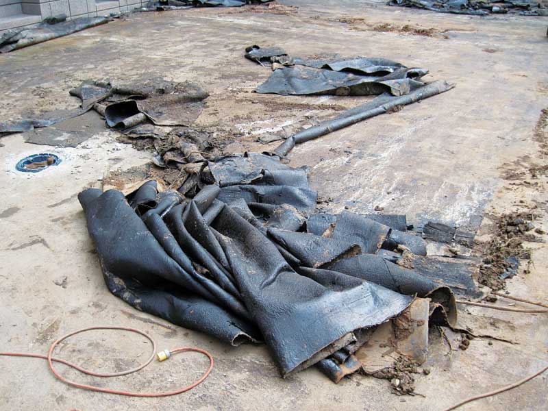
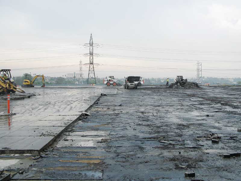
Rehabilitating a plaza deck over occupied spaces will almost always involve the full or partial removal of the existing membrane to repair the concrete substrate. In many instances, the existing waterproofing membrane is already deteriorated and leaks in several locations, but its complete removal can only increase the potential for water ingress during construction. If the entire existing membrane is not to be removed, it is extremely important for one to select a new one compatible with what is in place to prevent chemical attack to the new membrane. For example, bonded residue from a failed coal-tar membrane on the deck surface can chemically degrade many membrane types, including self-adhering bitumen sheets and hot-applied asphalt membranes.
Sign up for our weekly newsletter
Construction Canada weekly newsletters give the latest AEC industry news for those who build, design, engineer, specify, renovate or operate in the built environment.
Products & Services


Read the Latest Issue