Planning wi-fi systems in buildings
Cable connections
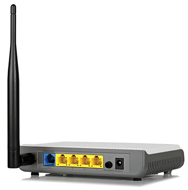
The AP requires one or two cable connections to operate. First is the Ethernet data cable which is used for the data transmission to the LAN or Internet. This cable is an appropriate fire-rated riser (FT-4/CMR cable), plenum (FT-6/CMP cable), or low-smoke-zero-halogen (LSZH) data cable for confined spaces. Typically, the Ethernet cable type used is Cat 5e, Cat6a, or Cat7, depending on the transmission rate and distance from the AP to the Ethernet switch or router. The maximum possible distance is 100 m (328 ft), but it can be less depending on factors such as cable type and transmission rate.
Longer data transmission distances can be achieved with repeaters or fibre optic cables. The second required cable is for power. This is typically a low-voltage cable, 12- or 48-volt type. APs that are power-over-Ethernet (PoE)-compliant—meeting IEEE 802.3af/at, CSMA/CD Access Method and Physical Layer Specifications Amendment 3: Data Terminal Equipment Power via the Media Dependent Interface Enhancements—can accept power through the Ethernet cable and only require one cable connection for both data transmission and power. If the data cable is not run in its own metallic conduit (dependent on electrical code), then shielded twisted pair (STP) data cables or fibre-optic cables can be used to reduce electrical interference from affecting the cable’s communication signal and reducing throughput.
The AP is carefully located and setup to provide maximum area coverage and connection speeds in the service area. Coverage area size depends on many factors including transmission data rate, frequency, and the environment. It can range anywhere from 170 to 400 m2 (2000 to 5000 sf) in open areas. The typical AP radio radiation pattern is omnidirectional (i.e. horizontal plane) and donut-shaped (i.e. vertical plane). Most are designed to be installed horizontally on a ceiling or vertically on a wall. It is important to ensure a horizontally mounted AP is not installed in a vertical position since the product’s antenna radiation pattern is optimized for horizontal mounting, which will consequently reduce the possible coverage. A good installation location to consider is on a room ceiling in the middle of the coverage area. However, this can change due to building infrastructure, esthetics, and practicality.
Signals and coverage
Wi-Fi radio signals are affected by all materials to some degree, which results in signal attenuation, scattering, and reflection. The greatest effects occur with conductive material such as steel, aluminum, copper cables, and concrete. This means the AP signal will be significantly attenuated by a concrete wall or floor, specifically with imbedded rebar. To reduce Wi-Fi signals attenuation between rooms, concrete (and concrete masonry units [CMUs]) are avoided. Walls can be constructed of wooden studs and drywall. The greatest coverage distance is typically achieved where direct line of sight between the AP and the mobile devices is possible without any nearby obstructions.
AP manufacturers design the unit to look appealing for it to be installed in plain view on the coverage area’s ceiling or high up on a wall. It can also be placed out of view, such as above a suspended ceiling if building codes permit, but the ceiling and supporting structures will affect the signal and the AP coverage area. For areas with small rooms, such as hotels, one AP may be able to adequately cover a room and adjacent rooms, but this depends on factors such as the space’s size and wall material.
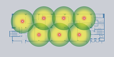
Due to the nature of construction materials typically used in commercial and industrial floor systems, multiple APs need to be deployed on each floor of the building to adequately provide floor coverage. It is possible to estimate AP placement location from building plans, but an onsite Wi-Fi survey is required to ensure the best results. This requires a technician to setup a temporary AP in the planned installation location and then walk around the coverage area measuring the AP’s wireless signal power. The technician also logs and investigates any interference that may cause problems with the communication link. Possible sources of interference include other nearby APs, microwave ovens, baby monitors, and cordless telephones. Ideal coverage will allow the Wi-Fi user to walk throughout the total coverage area without noticing any loss or degradation in service.
When planning Wi-Fi coverage for large areas such as atriums, courtyards, parking lots, and stadiums, more than one AP is required to provide adequate coverage for the area. AP locations are carefully planned such that their coverage areas overlap in order to avoid dead spots. Adjacent and nearby APs need to operate on different channels in order to avoid interfering with each other. If the Wi-Fi network is operating in the 2.4-GHz band, there are only three channels—1, 6, and 11—that do not interfere with each other and can be used for communication at speeds up to 50 Mbps. Switching to 5-GHz Wi-Fi operation increases the available number of communication channels to 21 and with higher available transmission speeds. However, the transmission range at 5 GHz is more limited than at the 2.4-GHz band. Further, many consumer Wi-Fi devices are not currently equipped for 5-GHz Wi-Fi communication.
Planning for secure networks
Another important point to consider when planning Wi-Fi communication is security. Wi-Fi AP signals are not limited by building confines and often can be measured in nearby public streets. The Wi-Fi standard body has recognized this fact and developed security protocols, which are imbedded into the AP’s and mobile’s firmware. If set up correctly, these processes provide secure and encrypted communication between the AP and wireless device.
The latest standard in Wi-Fi communication security uses Wi-Fi Protected Access II (WPA2) with Counter Cipher Mode with block-chaining message authentication code protocol (CCMP ) or Advanced Encryption Standard (AES) encryption. This protocol is thought to be practically impossible to break if properly setup. It requires a password to access the wireless network, referred to as pre-shared key (PSK) authentication. Once a device is authenticated and connected to the AP, the Wi-Fi wireless communication between the AP and mobile device is encrypted.
Password length for all connecting devices should be at least 30 characters in length, using a mixture of numbers, letters, and special characters. Since the password typically only needs to be entered once into the mobile Wi-Fi device, repeated long password entry is unnecessary. Short-length passwords have been compromised in the past. Maximum password length is 63 characters.
Commercial installations should use proper commercial AP with radius server security and not the commonly available pre-shared key (PSK) authentication type designed for residential applications. Commercial-grade APs also have more powerful processors and circuitry, allowing for more reliable Wi-Fi connections with better throughput.
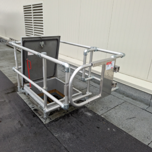
APs are mounted securely, high up and out of reach on sturdy building structures such as on room ceilings. This reduces the risk of someone easily disconnecting and removing the AP. Height also can increase the AP’s coverage area.
Placing the AP’s data and power cables in metallic conduit can help reduce the possibility of future cable damage during renovations or building alterations and of unauthorized access to the data network. It also may be a requirement by some building and fire codes.
AP transmission power should be lowered to the minimum power required for the coverage area. It is best not to use default power values, which are often set to maximum.
For high-security rooms or buildings where ingress and egress of all radio frequencies (including Wi-Fi) need to be reduced or eliminated, a Faraday cage is built surrounding the entire room or building. This is an enclosure completely covered by a conductive material such as wire screen mesh, steel, or aluminum foil. It may be less costly to plan and install it into new building construction then retrofit an existing building. Properly designed, this type of protective shielding is effective in reducing or eliminating Wi-Fi signals, RF signals, and any electromagnetic interference (EMI) from entering and leaving the enclosure. Partial Faraday shielding can also be used in walls, ceilings, and floors to reduce interference from nearby unrelated Wi-Fi systems or other interfering RF and EMI devices. It should be noted, this is also effective in blocking or limiting cellular and other radio signals from entering and leaving the protected building or room.
One can also consider using 5-GHz channels instead of 2.4-GHz channels, since this band’s transmission range is shorter and the wireless signal is better attenuated by a building’s brick and concrete walls.
Conclusion
Carefully planning of Wi-Fi deployment within buildings is key to providing secure, reliable, and ubiquitous coverage for all users. Building structures do affect Wi-Fi signal propagation and can increase or decrease coverage areas depending on building design. Wi-Fi communication is susceptible to many forms of interference including interference from the other nearby Wi-Fi systems and the rogue (i.e. unauthorized) APs. In areas where the Wi-Fi signal strength is weak, additional APs may help improve coverage.
 Bob Chomycz, P.Eng., has been involved in the design, construction, testing, and operation of many wireless, wired, and fibre-optic communication systems for over 25 years. He can be reached at bchomycz@telecomengineering.com.
Sign up for our weekly newsletter
Construction Canada weekly newsletters give the latest AEC industry news for those who build, design, engineer, specify, renovate or operate in the built environment.
Products & Services


Read the Latest Issue