Overcladding masonry facades: Additional practical insights
Teams considering using EIFS for a masonry overcladding application may refer, for example, to the EIFS standards originally published in 2009 and 2010 by the Underwriter’s Laboratories of Canada (ULC). According to the EIFS Council of Canada, the ULC standards have made “the use of a water resistive barrier (WRB) system with EIFS to create a drained cladding assembly over moisture sensitive substrates … a standard requirement for all EIFS applications.” Any moisture that may penetrate through failed sealants or through cracks or flaws within the applied system can become trapped, creating deleterious conditions.
Water penetration must be mitigated with drainage and drying, and that is what newer EIFS systems are designed to do: drain and dry. This makes properly designed, applied, and assembled modern EIFS products highly effective as overcladding solutions for structural masonry. It is an adaptable approach that can succeed regardless of texture, joint design, and fenestration detailing, with benefits ranging from elimination of water penetration to enhanced wall R-value.
Building teams should keep in mind the success of this approach hinges on a sound masonry wall, parged smooth, and free of contaminants. As outlined in ULC’s EIFS Standards, attempts to apply EIFS to masonry that is crumbling, spalling, loose, or cracked will likely result in system failure. Contractors and trades should consult the standards for all requirements of a successful application including dryness, temperature, substrate flatness and, perhaps most importantly, compatibility—combining elements of systems from different manufacturers can lead to unexpected and sometimes unsuccessful results.
Structural questions and budgetary concerns
With respect to the solid masonry school buildings which are overcladded with face brick, the design solution and detailing typically includes creating a brick shelf to support the face brick with modifications to the existing stone base. Above the first floor and grade level, where the new cladding must be attached directly to the existing backup wall, new relieving angles are attached to the load-bearing masonry wall to support the face brick. Note that structural engineers must verify the load-bearing capacity of the existing foundations and walls. Also, the design must consider the potential for the brick to expand, which can create tension and interactions with the attachment assembly.
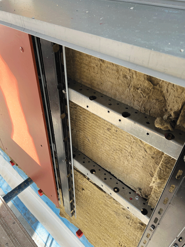
For rainscreen-style overcladding systems—whether insulated metal panel, panelized EIFS, terra cotta, or fibre cement board—the system generally is supported by a light-gauge metal subframe of either galvanized steel or aluminum. The subframe is cantilevered from the backup with a rail system or with adjustable brackets. In consultation with structural engineers, the sub-framing system must be designed to address dead load, wind load, seismic concerns, thermal expansion and contraction, and deflection for different backup conditions.
Regarding cost impacts, masonry overcladding solutions tend to be driven by budget-conscious solutions. For this reason, variations in costs associated with particular products or assembly components tend to be marginal, in the author’s experience.
Moving onto thermal bridging, metal frames, brackets, and rail systems do carry the potential for thermal transfer. Metal brackets and subframes attached directly to the masonry backup tend to conduct cold temperatures, contributing to the building’s heat loss. For these reasons, many manufacturers produce components made from low-thermal-conducting metals, and systems incorporated with thermal breaks. Whether or not the building team specifies products from one of these manufacturers, it is critical to design an assembly that includes thermal breaks in the subframe system to avoid thermal bridging, and to enhance the enclosure’s thermal performance.
Sign up for our weekly newsletter
Construction Canada weekly newsletters give the latest AEC industry news for those who build, design, engineer, specify, renovate or operate in the built environment.
Related Products & Services

Read the Latest Issue