The next generation of passive solar for cold climates
Reducing the glazing loss
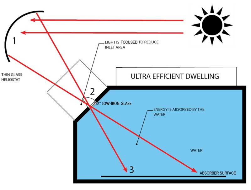
Decreasing glazing area decreases energy loss. By making heliostats adjustable and concave, more energy can be obtained through a smaller glazed opening or inlet accessing the thermal mass. To reduce energy loss at night and in cloudy periods, the glazing exposing the thermal mass could be covered with an insulated shutter.
Maximizing storage and spanning the seasons
One should take advantage of the Canadian summer sun, increasing the thermal mass and viewing the process as more of a long-term storage solution than a day-to-day one. This means heat would be collected in the summer, then stored in a highly insulated thermal mass and used in the winter. Water would be used instead of field stones because of its higher heat capacity, and circulation could be employed to transfer heat and minimize stratification (Figure 3).
The HelioArch
The team named the experiment the ‘HelioArch’—the next generation of active/passive solar for cold climates. The approach focuses on small-scale, dwelling-based installations. It is important to note, however, this method is not a novel one—solar thermal plants generating heat have been around since the early 1970s. Using water as a thermal mass is also a common concept. The critical element here is the system is designed to be integrated into the architecture of the building, balancing gains from the heliostats, the storage capacity of the thermal mass, and the losses routed to the dwelling.
In 2013, the team created the balancing software for the system, which modelled the thermal dynamics of a simulated environment. A computer model was created over a six-year period, using climatic data recorded by Toronto Pearson International Airport. (To view a sample of the software and continued research, visit www.helioarch.com.) The HelioArch software produced during this research models the hourly operation of the system over those six years, and the present version takes several issues into account, including:
- the area and number of heliostats;
- the type of heliostat;
- sky conditions (i.e. whether energy is available from the sun at that particular time and whether it is cloudy);
- whether the gains of the system outweigh the losses at a particular time;
- heat loss to the dwelling due to infiltration under the varying temperatures and wind from the climate data;
- heat loss to the building’s exterior due to conduction and convection under varying temperatures and wind velocities;
- the heat loss through the glazed inlet under the varying temperatures;
- heat gain from the heliostat;
- temperature limitations of the mass, as the charging of the mass is maintained between room temperature and the boiling point of water; and
- the heat loss of the assemblies under varying temperatures.
The program summarizes these components into a single heat loss/gain calculation, ultimately showing the final temperature of the thermal mass at the end of each hour over a simulated six-year period. The output is a graph showing the temperature of the thermal mass at any one time within the six-year period. It is critical the thermal mass and heliostat(s) are sized correctly to ensure the energy can be made available when it is needed. Figure 4 displays the output of the HelioArch software.
In Figure 4, one can see the heating and cooling of the thermal mass over time. The house modelled is approximately 167 m2 (1800 sf); thus, the thermal mass is close to 125,000 L (33,000 gal). The heliostat size must also be balanced in area to provide enough energy to span the seasons. The software simulates the shutdown of the heliostat system if the temperature approaches the boiling point of water, thereby avoiding the pressure issues associated with the phase change of water turning to a gas, and will also display a flatline graph if the system is undersized or oversized at any point.
Once the mathematical model had been reviewed by the team, prototyping and real-world testing commenced. In 2013, with the assistance of Toronto’s George Brown College, the team began creating scale models of the system to test the accuracy of the software. George Brown assembled the heliostat, as well as the tracking logic and mechanism to allow the Helioarch to follow the sun (Figure 5).
This led to a 1/8 scale working model test, completed by architecture professor Ramani Ramakrishnan and the fourth-year building science studio at Toronto’s Ryerson University in 2016. The experiment, conducted over eight hours on a sunny winter day, showed an increase in water temperature, using a 600-mm (23-in.) diameter concave heliostat and a 900 x 900 x 900-mm (35 x 35 x 35-in.) insulated thermal mass. The test mimicked the results of the software.
This winter, a ¼ scale model complete with an automated shutter and heliostats will be tested. In this model, the heated water will be circulated through a simulated dwelling using hydronic pipes in the floor. Cooled water will be returned to the energy storage tank in the building’s basement.
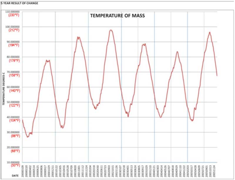
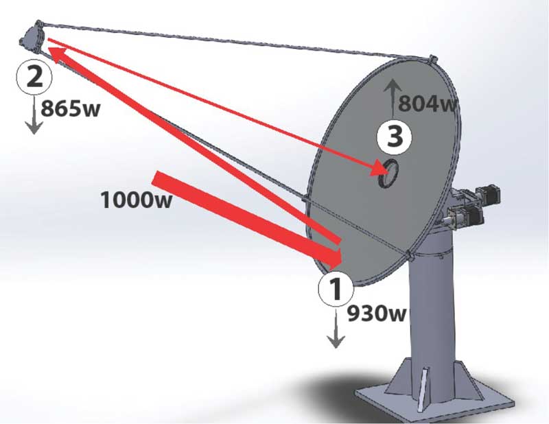
Image courtesy George Brown College
Sign up for our weekly newsletter
Construction Canada weekly newsletters give the latest AEC industry news for those who build, design, engineer, specify, renovate or operate in the built environment.
Products & Services


Read the Latest Issue