Masonry: 10 tips from the field
Tip 3: Use modular dimensioning
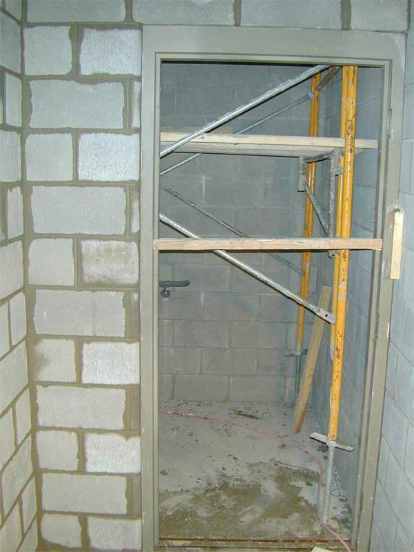
Modular design seems intuitive and natural, and masonry units lend themselves to the concept. Concrete masonry, for example, while available in many sizes and shapes, often is specified with a nominal 200-mm (8-in.) high x 405-mm (16-in.) long face dimension, with varying widths. One can save time and money by designing both height and length to this modular dimension when spacing openings. A concrete masonry unit (CMU) is one of the best bargains in construction, and a skilled bricklayer can install them rapidly. The cost rises quickly, however, when extra cuts and layout time are involved. In Figure 3 (page 32), the wall is off module and a bricklayer needs to measure and mark each cut, send the block to a saw, and have the extra expense of laying more units. In this case, each concrete block around the perimeter of the opening needed to be cut. If the opening could have been shifted only an inch or two, then there would have been a steady spacing of half and whole blocks. Add this up over many openings and costs can escalate.
A good concept used by estimators is the rule of 200-mm heights. If the foot dimension is an even number, then the height to stay on module is either the even foot or the even foot plus 200 mm. If the foot dimension is an odd number, the height to stay on module is the foot dimension plus 100 mm (4 in.). Any other height and costs increase.
This concept works for brick as well. On a recent dormitory project in Ohio, a plan review noted window dimensions were slightly off module. Shifting them fractionally preserved the design intent, but saved more than $10,000 on the bid cost for reduced cutting of brick.
Tip 4: Locate movement joints on the drawings
Some of the more popular questions the author’s firm (the International Masonry Institute [IMI]) receives revolve around movement control. Concrete products, including concrete masonry, tend to shrink as they cure and lose moisture. Clay masonry expands with moisture and experiences dimensional changes for thermal expansion as well. It is helpful to recognize that and note on the drawings, locations, and provisions for movement control. Placing this only in a specification can lead to confusion and potential cracks in the masonry system. Control joints should be placed at various intervals for concrete masonry, as it tends to shrink. Clay masonry should have expansion joints to allow small growth of the brick.
According to the Masonry Society (TMS) 402/602, Building Code Requirements and Specification for Masonry Structures, the masonry code referenced by the International Building Code (IBC), the coefficient of thermal expansion for clay masonry is 7.2 x 10⁻⁶ mm/mm/C (0.000004 in./in./F), which works out to roughly a 13 mm (0.5 in.) of growth over a 30-m (100-ft) span with a 38 C (100 F) temperature difference.
Tip 5: The mason contractor should not locate the movement joints
While IMI and other groups offer advice on standard spacing for control and expansion joints, and review specific projects to make recommendations for movement joint location, the ultimate responsibility is with the designer of record. Decades ago, the masonry building code understood this need. The code now contains provisions requiring the designer, not a contractor or other source, to locate and detail provisions for movement control in masonry. While trained mason contractors are an asset to the project, they may not know the design intent or how the walls were structurally designed.
Properly designed masonry works with the adjacent materials as a system to control moisture penetration, vapour, airflow, and energy transfer. Most problems in the enclosure occur where two dissimilar materials meet.
Tip 6: Pay extra attention to where dissimilar materials meet
It is important to take great care where dissimilar materials requiring installation by different trades meet. Specifications and contracts should carefully state responsibilities.
Putting masonry units together as a system is the next step toward high performance. Masonry walls fall into the general categories of barrier, cavity, or drainage and rainscreen walls, which are a refinement of the cavity wall system. The most common issue with any masonry wall system is water penetration. Building professionals tend to assume moisture intrusion is a result of wind-driven rain, but designers should pay attention to other sources, including rising damp, vapour diffusion, and airborne moisture that moves due to differences in temperature and pressure. With the rise in the use of air and moisture control systems and layers, there is an increase in moisture problems due to uninformed or incorrect placement of the air and vapour barriers, or unintended consequences of trapping moisture or vapour, and location of the dewpoint.
It sounds counterintuitive, but in a cavity or drainage wall one assumes moisture will find its way into the cavity. Brick themselves do not leak, but water can find a way into the system.
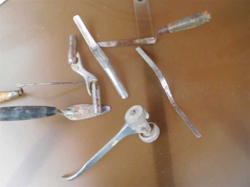
The first dissimilar material to investigate is the actual mortar joint. A mortar joint that is both tooled and compressed during installation is the first line of defense against moisture penetration. Figure 4 features a sample of mason tools used for tooling and compressing mortar joints.
Small hairline cracks in mortar joints are to be expected and should be no cause for alarm unless they grow to exceed roughly 1.5 mm (0.0625 in.). In that case, it should be looked at as a possible source of moisture, and the problem should be addressed in maintenance.
Assuming some amount of moisture will enter the masonry cavity, the strategy is for moisture to drain down the back of the veneer to flashing and weep vents. Flashing materials, and their installation, are the source of many long and detailed articles, so for this discussion, the author only wants to point out some common mistakes.
First, laps can cause leaking. Since most flashing systems require a lap from one section to another, this is a natural place for problems to occur. It is advisable to check the lap size and whether appropriate sealants were used. Most manufacturers will recommend anywhere from 50 to 150 mm (2 to 6 in.) for the lap. Based on jobsite experience, IMI recommends a minimum lap of 150 mm. This reduces the possibility of moisture travelling underneath the lap and also gives additional room for the installer to have some tolerance.
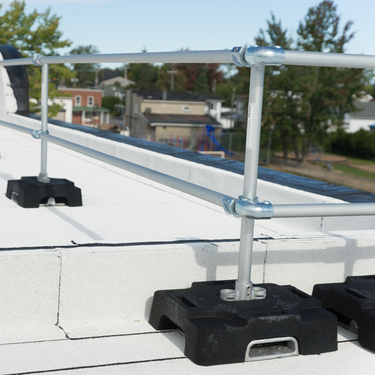
Check all flashings to see if there are penetrations. In many cases, the flashing is installed with the backup concrete masonry, with the intention to install the brick veneer later. This leaves some vulnerable types of flashing exposed to other trades prior to installation of the brick veneer. This can be addressed by either changing the sequencing or installing the flashing later with the brick veneer using a termination bar (Figure 5).
When using a termination bar, it is advisable to insist on a sealant bead across the top of the bar to resist water draining behind the flashing. Trade co-ordination in the masonry enclosure is critical.
Windows, doors, and changes in materials from brick to concrete, stone, glass, or metal are all potential areas for leaks. When two trades meet, there is always the possibility for a huge sealant joint due to tolerances or just poor co-ordination. This leads to another common issue: the size of the drainage plane, cavity, or air space itself. With various tolerances in the construction industry among steel, wood, concrete, and the masonry itself, one needs some room in the cavity between the back of the brick and the face of the backup material. Building codes call for a 25-mm (1-in.) minimum cavity dimension. While this may seem generous, consider various tolerances and the possibility for mortar droppings or other construction debris to fill a cavity. The author’s firm recommends a 50-mm air space independent of any insulation in the cavity.
A 50-mm air space has positive effects, including:
• promoting airflow through the cavity, a first principle towards rainscreen construction; and
• allowing for some level of mortar droppings.
A good cavity should be “clean, but not pristine.” Craftworkers trained by the International Masonry Training and Education Foundation (IMTEF) are taught to minimize droppings through good workmanship, but also to have a full head and bed joint.
Sign up for our weekly newsletter
Construction Canada weekly newsletters give the latest AEC industry news for those who build, design, engineer, specify, renovate or operate in the built environment.
Products & Services


Read the Latest Issue