Maintaining Lab Activity During an HVAC Retrofit: Challenges and opportunities with McGill’s Otto Maass Building
By Claude Giguère, Eng., FCSC, LEED AP, and Pierre-Luc Baril, Eng., HFDP, LEED AP
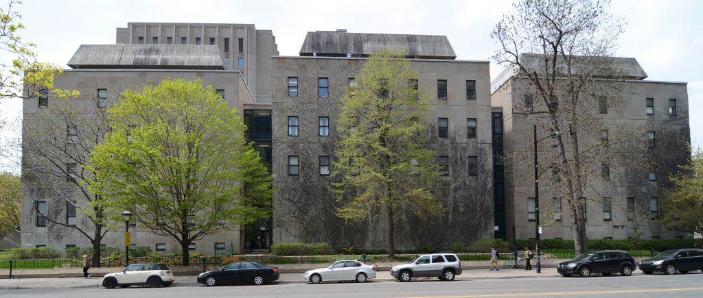
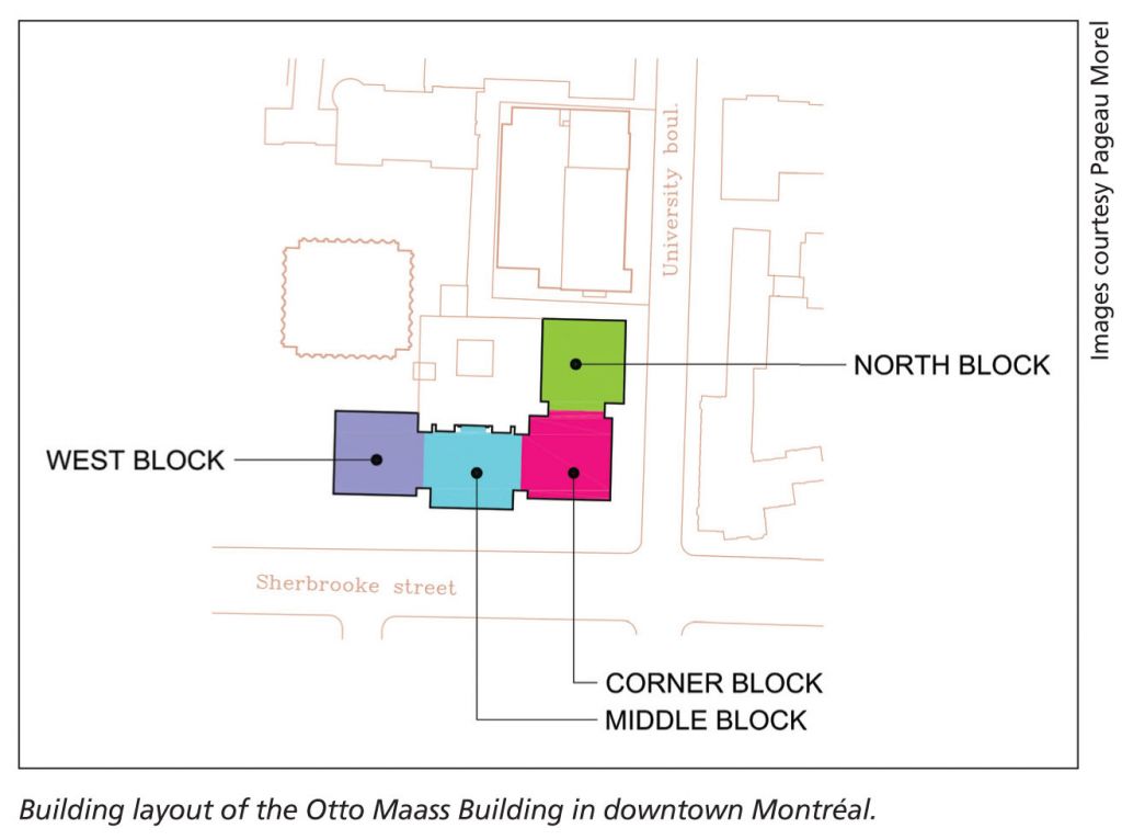
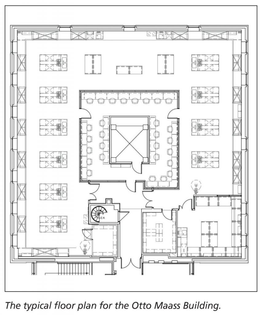
Built in 1964 within McGill University’s downtown Montréal campus, the Otto Maass Building is dedicated to graduate and post-graduate education research chemistry. It contains 235 chemical fumehoods over a total gross floor area of 11,617 m2 (125,000 sf). The average fumehood density is of 1 hood per 47 m2 (500 sf) of gross area, including offices and mechanical rooms.
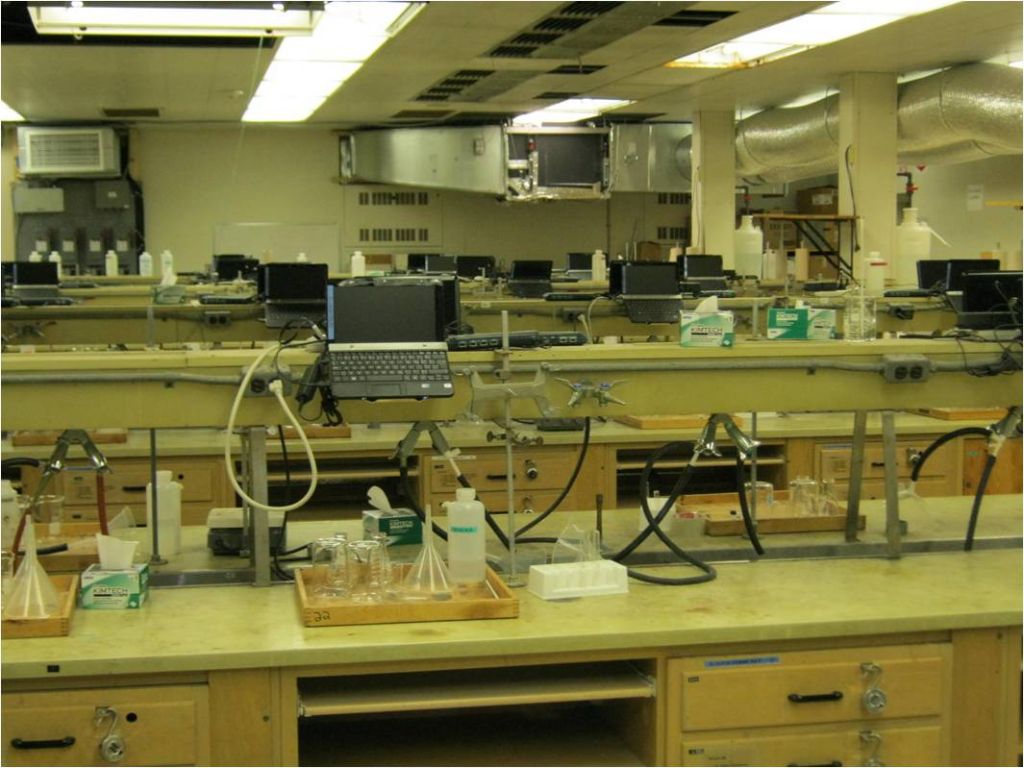
Before renovations, this building was by far the biggest energy-consumer on the McGill campus, accounting for 12 per cent of total energy use over only 1.9 per cent of total floor area. Mechanical systems had not been renovated since construction, and there were no energy-recovery devices. Additionally, air quality was deficient both within laboratories and at the outside perimeter of the building, affecting the safety of McGill chemistry staff, students, neighbours, and passersby.
 In 2009, the federal government announced a $2-billion plan—the Knowledge Infrastructure Program (KIP)—targeting renovations in colleges and universities. McGill decided to apply a portion of its allocation to the Otto Maass Building by renovating all mechanical rooms and service shafts serving laboratories, as well as 3485 m2 (37,500 sf) of laboratory space.
To comply with the initial program requirements, McGill had to complete the building’s renovation within 18 months, including conceptual and design phases. In this timeframe, and considering the type of research and teaching, it was not feasible to move the researchers elsewhere and to vacate the building because swingspace for these types of laboratories is both rare and expensive. The project had to be executed while the building was almost fully occupied. This presented a level of complexity similar to replacing an engine on a car while it drives down the highway.
Amongst the professionals working on the project, the belief held was the building would be extremely difficult and risky to renovate—not only because of these conditions, but also because some of the building components were covered with asbestos. However, the users, the McGill representatives, and the project manager wished to keep the project going. They knew they could potentially lose a large portion of the government funds if they did not deliver on time. They were comfortable with the risks involved and were ready to deal with the major constraints that would be imposed during renovations. They asked the professionals to develop a strategy that could be applied to handle impediments and provide contingencies.
 The plan
Early on in the design phases, charrettes were held for an integrated approach not only with the design team (e.g. architect, mechanical, electrical and structural engineers, asbestos consultant, project manager, and facilities management representatives), but also with the numerous stakeholders of the project (e.g. users representatives, operation and maintenance group, energy managers, environmental health and safety officers, waste management and fire prevention offices). These meetings helped outline various project goals and challenges, and unified and optimized everyone’s needs. Early in the conceptual phases, an energy-recovery opportunity was identified based on the understanding another project was taking place in a major server room located in the nearby Burnside Building. The opportunity offered the possibility to transfer approximately 300 kW of wasted heat (year-long) to the Otto Maass Building for terminal reheat purposes.
The strategy developed to handle the project did two things. First, it divided the project into various bid packages. In fact, a total of 10 packages were created to break down the renovations at the Otto Maass Building. Second, the strategy included the preordering of equipment with lengthy lead times. Ventilation units (supply and exhaust), exhaust fans, laboratory furnishings, and chemical fumehoods were ordered before the call for tenders so they could be manufactured while the design was still ongoing and while the contractors would be bidding on the project. These items were then transferred to the chosen contractor (the lowest ‘prequalified’ bidder) so he could become responsible for these items.
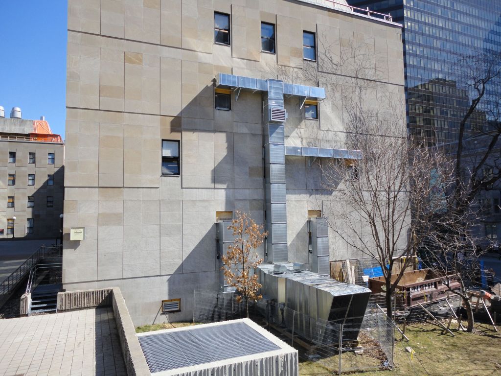
In conjunction with the main strategy developed, a construction package was issued to a separate contractor during the design phase to cover the installation of a temporary ventilation system throughout the building. This allowed the mechanical system to be demolished early in the project without interrupting laboratory usage. Temporary systems supplying 56,600 L per second (120,000 cfm) of 100 per cent fresh air were installed to supply the occupied laboratories.
 Aware the central services shafts would have to be demolished, the distribution of this temporary ventilation was achieved by securing ducts to the exterior of the building and by going through existing windows to reach the various locations requiring a supply of air. Flexible ducts were also employed within the spaces to reach specific areas. The four temporary ventilation systems were used during the construction phase—which included winter periods with outdoor temperatures reaching as low as −29 C (−20 F).
Certain fans were also installed early in the project to provide some lab-exhausting capability, and pressurization controls were integrated to modulate the exhaust. The rest of the required exhaust capacity came from the existing units, which had to be kept in working conditions during a portion of the main project.
Construction work
During construction, there was nearly no complaints from users regarding the quality of the air supplied by the temporary systems. In fact, to everyone’s surprise, indoor air quality (IAQ) achieved with the temporary setup was a lot better than it was before the project started.
The renovated laboratories represent nearly half of the building’s total laboratory area. As it was not possible to simultaneously renovate all the laboratory space, the work had to be planned in phases where users were moved from one area to another as soon as the renovation of a laboratory was completed. (Some users had to move their research setups more than once during the renovations.)
One of the biggest challenges besides managing the renovations of an occupied building was to fit everything in the three existing mechanical penthouses, each one having a footprint of only 230 m2 (2500 sf). In fact, the new systems took a lot more space than the old ones they were replacing because of the added heat recovery devices and the more efficient low-velocity design (greater face area inside the unit meant a bigger unit for a given flow). Therefore, larger equipment and ductwork needed to be installed.
Fitting everything in the tight areas available was achieved by optimizing the space and defining a diversity strategy for the fumehoods with the users. Such a strategy involves reducing the usage of hoods from full flow (100 per cent) to partial flows most of the time. A 60 per cent diversity was agreed on. This meant a maximum of 60 per cent of the fumehoods could be used simultaneously at full exhaust flow.
At the end, a total of 70,800 L per second (150,000 cfm) of capacity was installed—six supply systems of 11,800 L per second (25,000 cfm) each and 100 per cent fresh air, and six exhaust systems of similar capacity. The energy-efficient mechanical systems include:
- variable air volume (VAV) controls;
- direct-drive fans;
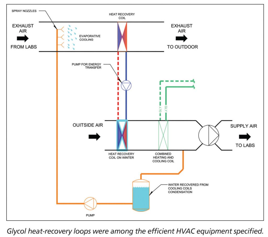
- run-around glycol heat-recovery loops;
- low-velocity systems;
- manifolded distribution networks;
- high-dilution fans; and
- low-temperature terminal reheats.
These terminal elements are heated by a low-temperature water loop that extracts heat from laboratory equipment rooms and from the major server room located in the nearby Burnside Building. The heat recovery loops are used all year long.
In winter, the system’s fresh air supply is preheated by the energy in the exhaust air through an energy-recovery loop. In summer, the reverse process occurs, but is much less efficient. To increase the energy transfer rate, the temperature in the exhaust air stream is first lowered by evaporative cooling approach. This process uses the water recovered from the condensation on ventilation units cooling coils that would have normally been sent to the waste drains.
Achieving success
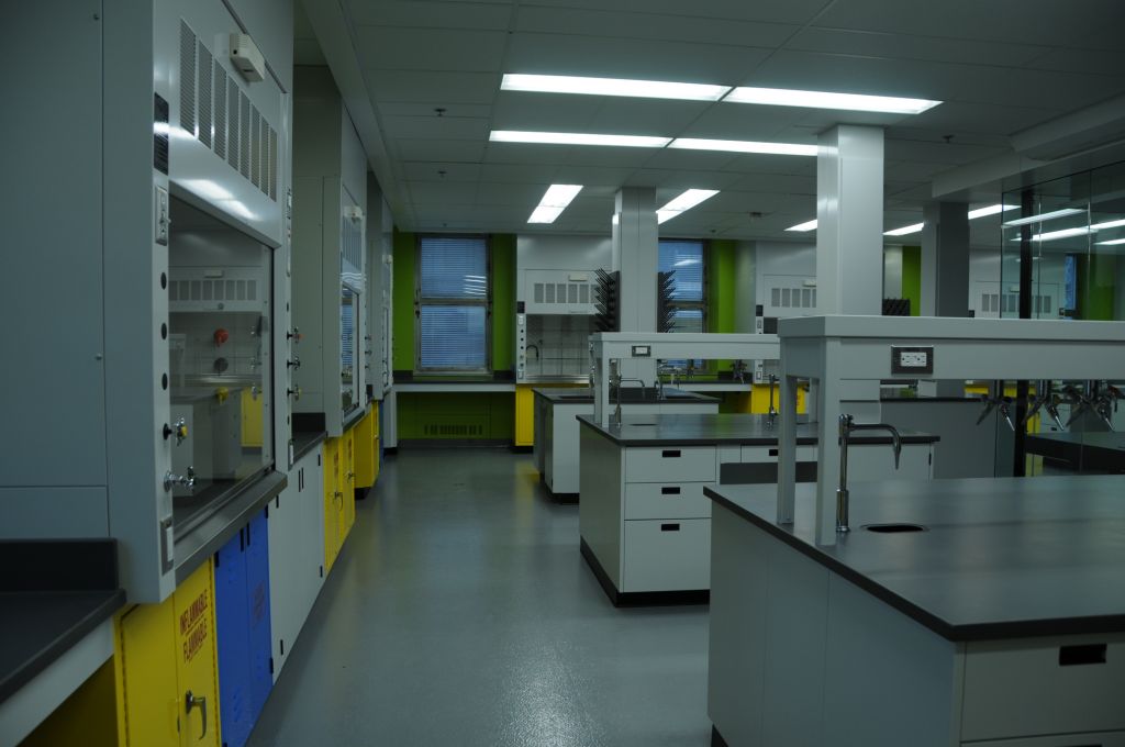
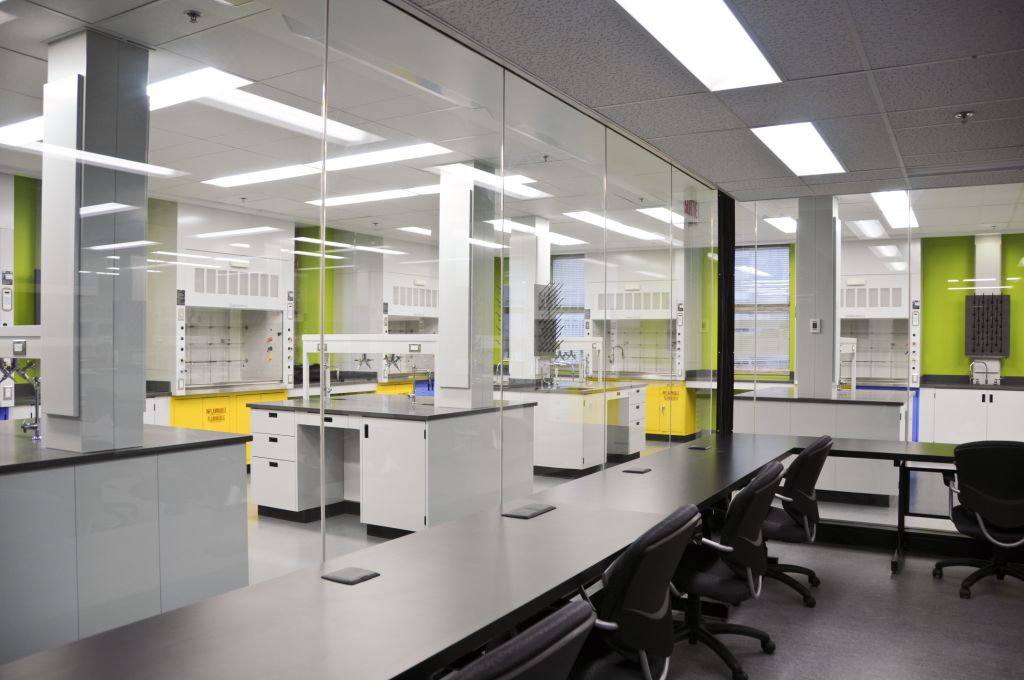
The laboratory renovation focused mainly on the retrofit of graduate research laboratories each equipped with 18 hoods, resulting in a density of one per 18.5 m2 (200 sf) of net lab area. The main goal was flexibility of use. The old laboratories were designed for unique purposes that were costly to adapt for varying needs. The new laboratories needed to simultaneously accommodate different types of research.
The retrofit was planned with a core workbench area surrounded by fumehoods along the outside walls. A glass partition wall was installed between the laboratory area and the write-up area, creating two distinct but communicating zones. Hence, students and researchers could safely work, take notes and see what is happening in the lab without being in laboratory space. Although the two zones are independently ventilated, air from the write-up area is first sent to the laboratory area before being exhausted, resulting in a reduction of the total amount of costly fresh air treated by the ventilation units.
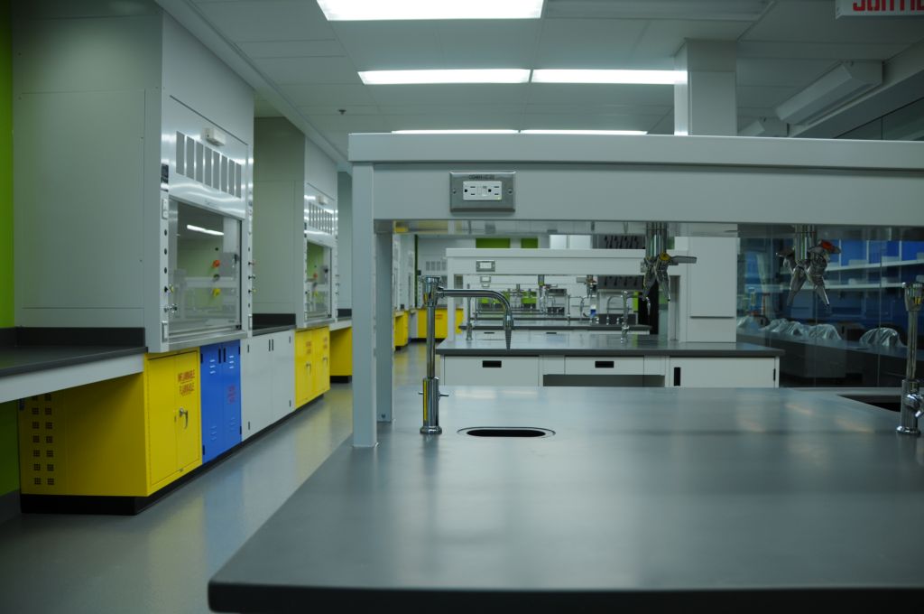
Laboratory hoods were replaced by modern VAV hoods modulating exhaust flow with regard to sash position (height). The hoods are also equipped with motion sensors that modulate the face velocity at the hood from 0.3 m per second (60 ft per minute) when not in use to 0.5 m per second (100 ft per minute) when operated. When a user stands in front of the hood, the face velocity automatically increases to ensure potentially toxic vapours are contained within the hood.
Any laboratory equipment that generates a lot of heat was located in dedicated equipment rooms. The heat dissipation is recovered by heat pumps connected directly to the low-temperature terminal reheat network. Finally, a storage room was added to each laboratory area to isolate chemicals not being used, reducing the chemical load and required ventilation in the actual laboratories.
To optimize energy consumption, a building automation system controls all parameters of the mechanical and electrical systems. Motion sensors automatically adjust air changes per hour (ach) and lighting in all areas depending on whether the area is occupied. Perimeter areas with windows have integrated motion and daylight sensors that function on the same basis, but with the added control of lighting according to the intensity of natural light.
A large portion of the building’s controls is related to fumehood operation. When a fumehood’s sash is opened or closed, the air flow to the laboratory space must be adjusted to rebalance the air flows inside the room. An anticipation control was implemented to reduce air temperature variations cause by the rapid hood sashes opening.
User comfort and safety were two of the main issues when designing. User participation was also deeply thought out to prevent energy waste. Students, professors, researchers, and other users were educated and informed about the energy consumption and associated cost of a hood sash left open on a non-used hood. This was done to encourage them to close sashes as soon as they walked away from the hood.
During the project, energy meters were installed to monitor the energy consumption of the building via an energy management software already in use at McGill. Further, commissioning was done once construction was completed to optimize every energy aspect of the various systems. This ensured the university obtained the most energy-efficient chemistry facility possible.
Even without the capacity to improve any components from the building’s envelope, these various measures lowered the annual energy bill by $1.3 million—a 59 per cent reduction. This is in line with early energy calculations during the design phase, which predicted energy reductions of 50 to 60 per cent. Pre-project building energy consumption represented about 12 per cent of the total energy consumption of the downtown campus. The renovated building energy consumption now represents about four percent of that total, which is equivalent to a reduction of about 3000 annual tonnes of carbon dioxide (CO2).
Conclusion
The construction cost was around $14 million. Unlike previous years, systems are now easily maintainable, indoor and outdoor air quality has dramatically improved, and McGill now has more versatility in how laboratory spaces are assigned to researchers with continuously changing needs. Additionally, the integration of larger system capacities than were required at present is available for use in future renovations.
This year, the project was awarded with an Honorable Mention in the Existing Educational Facilities category at the 2014 International Technological Awards hosted by the American Society of Heating, Refrigerating, and Air-conditioning Engineers (ASHRAE). It was also awarded with an Honorable Mention in the Existing Institutional Building category at Association québecoise pour la maîtrise de l’énergie’s (AQME’s) 2013 Energia Awards—a testament to its technical expertise in energy efficiency and sustainable design.
 Claude Giguère, Eng., FCSC, LEED AP, is vice-president and associate at Pageau Morel et associés inc. in Montréal. He has more than three decades of experience in consulting engineering. Giguère was president of CSC for the year 2012−2013, and became a member of its College of Fellows earlier this year. He can be reached at cgiguere@pageaumorel.com.
 Pierre-Luc Baril, Eng., HFDP, LEED AP, is an associate at Pageau Morel et associés inc. in Montréal and is specialized in designing energy-efficient laboratories. He is certified as a healthcare facility design professional (HFDP) by the American Society of Heating, Refrigerating, and Air-conditioning Engineers (ASHRAE). Baril is actively involved in the executive committee of CSC’s Montréal Chapter. He can be contacted at plbaril@pageaumorel.com.
Sign up for our weekly newsletter
Construction Canada weekly newsletters give the latest AEC industry news for those who build, design, engineer, specify, renovate or operate in the built environment.
Products & Services


Read the Latest Issue