Integrating mass timber in low-rise construction
The posts are storey-height, with the beams connecting to their vertical faces. This enables the bottom of the upper floor posts to bear directly on the posts below, eliminating cross-grain material from the vertical load path and minimizing the shrinkage effects. The connections between upper and lower posts use embedded steel rods glued in place with epoxy. Post-to-beam connections vary according to location. Where appearance is critical, concealed connectors are used. These steel connectors consist of two steel plates, one screwed into the face of the post and the other into the end of the beam. When brought together, they interlock to complete a concealed connection, protected from fire by the surrounding wood. Where the connections are not visible, more traditional steel-bearing plates have been used.
The floor consists of seven-layer, 245-mm (9.6-in.) thick CLT panels laid in the east-west direction and typically spanning 7.5 m (24.6 ft). The roof panels are also seven-ply as they support the soil and plant material forming the green roof.
The floor and roof panels bear directly on the beams and are secured by long stainless-steel screws. Plywood splines are used to bridge the joints between panels, enabling the floor system to act as a diaphragm and contribute to the lateral system in the building. The 25-mm (1-in.) thick plywood splines are rabbeted into the top layer of the CLT and screwed in place, as no concrete topping is used.
The floor system connects to two steel stair cores in diagonally opposite corners of the building. Other vertical elements contributing to the building’s lateral stability are concealed within partition walls. Buckling restraint braces are in the east-west walls of the stair cores, and where needed within north-south walls.
Where bracing was needed and could not be concealed, exposed steel “omega” bracing is used. These braces run vertically through the building and consist of two sculptural steel elements with a connection between them that provides the necessary ductility. A custom solution of a more traditional eccentrically braced frame, the name was coined by the design team because of the resemblance to the Greek letter “Ω.”
Detailed co-ordination was required between the structural engineer, architect, and mechanical consultant, as there were several locations where sprinkler pipes had to be threaded through glulam beams. Generally, the strategy for integrating building sprinkler systems was to run the main lines along the narrower structural bays at the rear of the building, where the shallower beam depths enabled them to be partially concealed when viewed obliquely from below. Only small diameter branch lines had to be run below the main beams.
The goal
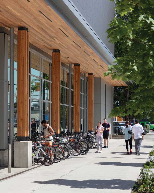
The goal for this project was a flagship store that captured the outdoor spirit and responded to the environmental concerns of the MEC community. As Hugh Cochlin of Proscenium states: “The proximity to cycling paths, the seawall running route and kayaking opportunities on False Creek, the store benefits from the energetic and active environment literally all around it. The architectural expression, with its sloping green roofs, blurring of the indoor-outdoor experience, tall wood structure, and images of the mountains beyond speaks to MEC’s outdoors spirit and acts as a perfect gateway to the neighbourhood.”
Fast + Epp home office
Just a few blocks from the MEC store, the new Fast + Epp home office also uses CLT and glulam in an elegant and economical solution, reflecting the design philosophy of the structural engineering practice.
The four-storey mixed-use building is in an eclectic light-industrial area which has undergone dramatic transformation over the past decade. The 37- x 13.7-m (121- x 45-ft) site is zoned for a floor-space-ratio (FSR) of 3.0, out of which 1.0 must be an industrial use located at street level. The presence of a 1.2 m (4 ft) right-of-way reduced the width of the site, forcing a portion of the industrial use to the second level and making vertical fire separations necessary.
Below grade, the reduced width required the elimination of interior columns in favour of a clear span, post-tensioned slab, to accommodate two rows of parking with a central aisle. This influenced the design of the above-ground structure, where clear spanning glulam beams informed both the subdivision of space and the routing of exposed building services.
These constraints required a rigorous design response, leading to simple, practical, and economical solutions in their use of space and materials. This resonated with Fast + Epp, both client and structural engineer for the project, and with f2a architecture.
To maximize leasable area within the FSR and height limits, floor-to-floor heights were carefully manipulated according to use; level one being 4.8 m (16 ft); levels two and three being 3.6 m (12 ft) and the level four penthouse being 2.6 m (8.6 ft). There
is an interconnected floor space (IFS) between levels three and four. There is a two-hour fire separation between industrial and office occupancies, with one hour required for the other floors and supporting structure.
The IFS forms an atrium, serving as a meeting area and social space for the office. The lower level has a small kitchen, while the upper level accommodates “touch down” workstations—which are common unassigned desks in open plan offices—and, being smaller than the lower floors, it has access to a roof terrace.
Egress stairs, elevators, and a vertical service shaft are in the southeast and northeast corners of the building, adjacent to the lane. These form bookends to the north-south distribution bulkhead, where most of the north-south services run under the transverse glulam beams. East-west electrical and mechanical services run in the spaces between these beams, making them as unobtrusive as possible.
Sign up for our weekly newsletter
Construction Canada weekly newsletters give the latest AEC industry news for those who build, design, engineer, specify, renovate or operate in the built environment.
Products & Services


Read the Latest Issue