Influence of gaps on roof insulation performance
Dimensional stability
Images courtesy National Research Council Canada
 Dimensional stability is sometimes confused with thermal expansion. Dimensional stability is a property found in product standards for insulation materials as well as for other roofing or building enclosure materials. It is a test for measuring the permanent deformation of a material after exposure to extreme conditions. In the case of insulation materials, dimensional stability is technology dependent, and has to be tested according to the product specification covering the type of insulation. In all cases, dimensions of the specimen are measured before and after the exposure period, once it has reached room temperature again. For EPS, the Canadian standard is Underwriters Laboratories of Canada (CAN/ULC) S701.1, Standard for Thermal Insulation, Polystyrene Boards. This standard requires EPS to be tested for dimensional stability by exposing a specimen for seven days at 70 C (158 F) (dark oven, no specific moisture level), and then letting it cool down to room temperature and measuring any change in dimension. The standard limits the change in dimension for EPS to 1.5 per cent.
In the case of polyiso, the standard of reference in Canada, CAN/ULC S704.1, Standard for Thermal Insulation, Polyurethane And Polyisocyanurate, Boards, Faced, has different requirements. Polyiso must be exposed to three different conditions when testing for dimensional stability. Those three conditions are independent and require a different specimen for the test. The maximum allowed change in dimension is 2 per cent. The first condition is a cold temperature exposure (seven days at –29 C [–20 F]); the second is a longer, dry heat exposure (28 days at 80 C [176 F]); and the third is a long, humid heat exposure (28 days at 70 C [158 F] and 97 per cent relative humidity [RH]).
Dimensional stability tests need to be performed by the manufacturers to document compliance to the product standard. Although the standard allows up to 2 per cent change in dimensions, typically less than 0.5 per cent change is measured for good quality polyiso. However, if design professionals take the maximum 2 per cent change, the potential net effect is 24 mm (0.95 in.) of shrinkage for a 1.2 x 1.2-m board.
Shrinkage due to moisture
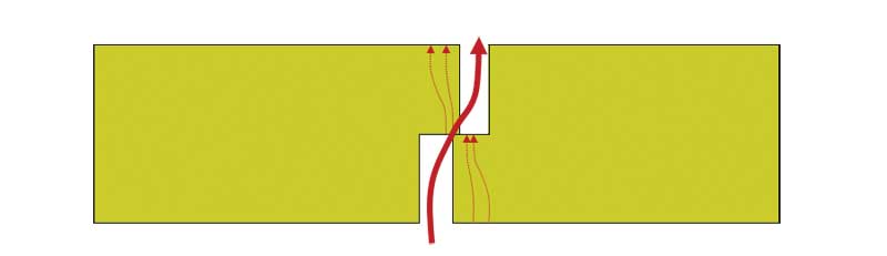
Mechanically attached roof assemblies may be subjected to moisture accumulation within the insulation layer under the roof membrane. When the membrane billows due to uplift pressure generated by wind, it acts as a diaphragm and pulls air from the interior, conditioned space to the unconditioned space in the insulation layer. When the deck-level vapour barrier is not perfectly airtight, this air brings moisture that condenses at colder temperatures on the underface of the roof membrane. Even if the moisture is allowed to escape the roof assembly during the summer months, Molleti et al. (2015) showed insulation materials had been slightly affected and small gaps (up to 13 mm [½ in.] in the case of polyiso) appeared between insulation boards (For more information, refer to “Impact of Air Intrusion on Moisture Performance of Seam-Fastened Mechanically Attached Roofing Systems” by S. Molleti, B. Baskaran, P. Kalinger, M. Graham, J.-F. Côté, J. Malpezzi, and J. Schwetz, presented in 2017 at the 15th Canadian Conference on Building Science and Technology).
Heat flow meter testing
To evaluate the impact of the presence of gaps between insulation boards to the thermal performance of roof assemblies, two types of testing—small-scale, heat flow meter testing as well as a larger, hot box testing—were performed.
The heat flow meter is a small-scale test routinely used to measure R-value of materials. This test is referenced in all insulation standards for the determination of their R-value. Testing was done on polyiso according to ASTM C518, Standard Test Method for Steady-State Thermal Transmission Properties by Means of the Heat Flow Meter Apparatus. The heat flow meter has an insulation specimen positioned between cold and hot plates. Since there is a difference in temperature of the plates, a heat flow is induced within the insulation material. This heat flow is measured and converted into thermal resistance (R-value) of the specimen. The temperature differential is essential for the test because without it, there would be no heat flow through the specimen, hence it would be impossible to report a R-value. Consequently, the R-value obtained from heat flow meter testing is expressed with respect to a mean temperature, which is the average temperature between the cold and hot plates.
Specimens of polyiso with thickness ranging from 63 to 150 mm (2.5 to 6 in.) were tested in this study. Specimens measuring 300 x 300 mm (12 x 12 in.) were used in the heat flow meter except for 150-mm thick specimens, which required larger specimens (600 x 600 mm). Tests were performed at 24 C (75 F) mean temperature (cold plate at 13 C [55 F] and hot plate at 35 C [95 F]).
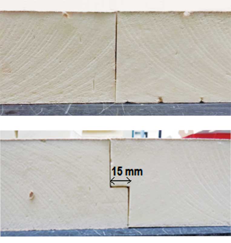
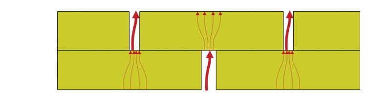
A reference test was done on an integral specimen (a full specimen without a joint), to which all other tests would be compared. Testing continued using specimens with joints and creating gaps in the specimens. Straight and shiplap joints (with 15 mm [591 mils] lip size) were compared (Figure 2). Closed joints as well as joints with gaps of up to 25 mm (1 in.) were tested for comparative purposes up to the maximum shrinkage allowed by the standards, even though such large gaps are rarely seen in the field.
Specimens measured with a joint needed their R-value to be normalized. In the heat flow meter equipment, the joint is present on a 300-mm wide piece of insulation. On a roof, the same joint would be present for a 1220-mm (48-in.) wide board, so the joint’s influence on the overall thermal performance is greater for the heat flow meter result than it is on the roof. The R-values obtained from the heat flow meter were therefore normalized for a 1.2 x 1.2-m (4 x 4-ft) board size using an equation found in Burch et al. (1987) and assuming only a one-dimensional heat flow (ignoring any convection, conduction, and side effects). For more information, read the 1987 paper “A Heat Transfer Analysis of Metal Fasteners in Low-Slope Roofs” by D. Burch, P. Shoback, and K. Cavanaugh for selected technical papers (STP) 959 Roofing Research and Standards Development, edited by R.A. Critchell for ASTM International.
Normalized results of the heat flow meter testing are presented in Figure 3 . Reference R-values for the integral specimen increase from 16.4 to 40.7 depending on thickness, predictably. Also indicated are the R-values of specimens with joints (but closed gap), and with gaps up to 25 mm (1 in.), for both straight and shiplap joints.
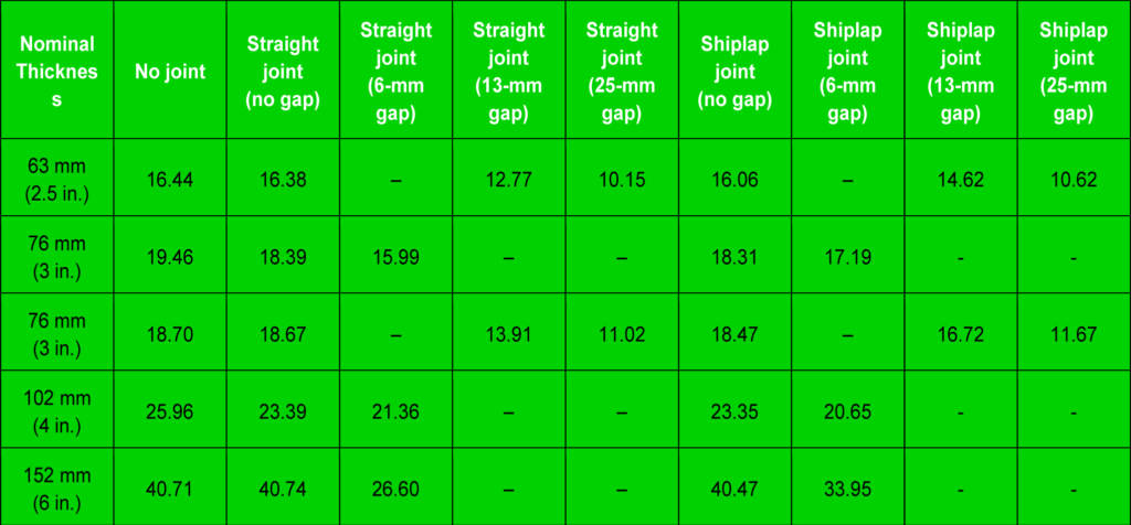
As expected, the R-values obtained on specimens with closed joints are lower than the reference. The difference is not large, reaching no more than 10 per cent reduction over the reference value. Interestingly, results seem to indicate straight joints perform better than shiplap joints when no gap is present. However, the largest difference is seen with the 63-mm (2.5-in.) thickness and is below 2 per cent, which cannot be considered meaningful. When gaps open to 6 mm (236 mils), results begin to favour the shiplap joint configuration as two results out of three indicate a better retention of R-value for shiplap over straight joints. This is especially true at the thickness of 152 mm (6 in.) where the shiplap specimen retained 83.4 per cent of the reference R-value and the straight joint specimen retained only 65.3 per cent. At 13 mm (½ in.) gap size, the dominance of shiplap configuration is obvious (89 over 75 per cent retention for straight joint). If gaps open more than 13 mm, the shiplap no longer functions as such (current specimens had a 15-mm [591-mils] lip) and both joints provide about the same R-value despite a little advantage for the shiplap (63 per cent retention compared to 61 per cent for straight joint).
These results are only indicative because the straight joint configuration is not representative of reality. As mentioned earlier, there are usually two layers of insulation on top of one another in a roof system. The joints are staggered so if a gap opens between boards, the gap on the top board is never positioned over the gap on the bottom board.
Sign up for our weekly newsletter
Construction Canada weekly newsletters give the latest AEC industry news for those who build, design, engineer, specify, renovate or operate in the built environment.
Related Products & Services

Read the Latest Issue