Improving continuous insulation
Comparing methods of construction
How can different components affect the overall thermal transmittance of a wall assembly? A comparison of brick and EIFS wall sections at a floor line illustrate how the variables can change design decisions.
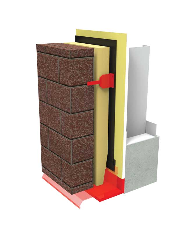
Brick veneer wall assemblies supported by steel shelf angles are a common wall construction (Figure 4). Exterior insulation, often 50 mm (2 in.), has been used to produce a nominal RSI 1.4 to 1.76 (R-8 to R-10) value. The thickness and subsequent R-value are limited by the size and projection of the shelf angle.
The insulation is not continuous, of course, because of the projecting shelf angle. If the steel stud cavity has batt insulation, then a nominal RSI 2.1 (R-12) for a 92 mm (3 5/8 in.) stud space is added. Considering the insulation alone, this could be a nominal RSI 3.9 (R-22) wall.
Until recently, the thickness of the steel shelf angle was considered a minor thermal bridge through the insulation, because the cross-sectional thickness of the steel shelf is relatively small compared to the area of the wall. However, the Morrison Hershfield research has shown this thermal bridging effect can reduce the effective R-value of the ‘clear wall’ by more than 30 per cent. Since many variables affect this calculation, practitioners who want to work out the linear transmittance for their design should refer to the BETB Guide.
The effective thermal performance of this design can be improved with more energy-efficient details. For example, moving the shelf angle out from the wall using clip assemblies (e.g. knife plates, hollow structural steel [HSS] sections, or overlapping angles) reduces the area of thermal bridging. Continuous insulation (ci) can be installed between the shelf angle and the wall. Optimized clip design, spacing, and materials can improve thermal performance to a 15 per cent reduction of the ‘clear wall’ value. Using proprietary insulated connections will also bring the thermal transmittance closer to the ‘clear wall’ value. (The paper, “Masonry Veneer Support Details: Thermal Bridging”, was presented by RDH Building Engineering Ltd.’s Michael Wilson, M.Eng., Graham Finch, MASc, P.Eng., and James Higgins, Dipl.T, at the 12th Canadian Masonry Symposium, held in Vancouver in June 2013.)
An additional consideration for brick veneer is the choice of brick ties. Once again, the cross-sectional area of the tie as a ratio of the gross wall area might appear insignificant in terms of its thermal bridging. A paper published in 2013 suggests this assumption would be a mistake and that, based on tie material and design, the effective R-value reduction of the exterior insulation could be from five to almost 30 per cent. (“Thermal Bridging of Masonry Veneer Claddings & Energy Code Compliance” was presented by the same authors at the same conference as in Note 4.)
The brick wall in Figure 4—from sheathing to outer face, with 50 mm (2 in.) of continuous insulation—could have a dimension of approximately 180 mm (7 in.) with an approximate effective RSI 3.2 (R-18) value (versus a nominal RSI 3.9 [R-22]). To achieve this effective R-value, all the design improvements would have to be made to the details. This would meet the 2015 NECB requirements for the lower mainland of British Columbia. Other regions would have to increase the continuous insulation value. Again—designers should make their own calculations based on the BETB Guide.
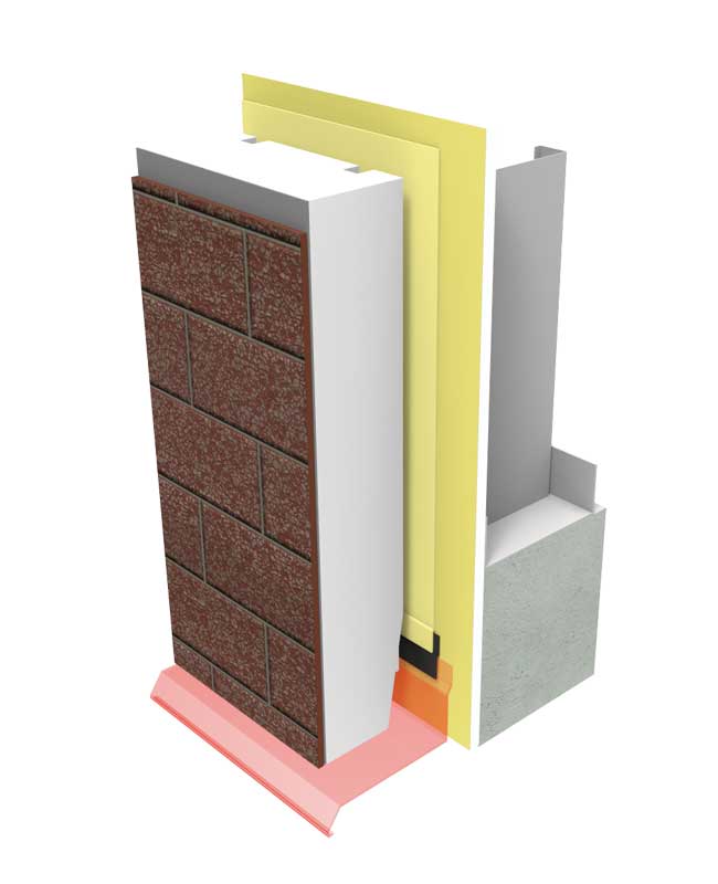
EIFS offers an alternative method of construction with a number of thermal advantages over the brick veneer wall. Since the assembly is adhesively secured, there is no thermal bridging through fasteners. EIFS is also self-supporting, so there is no need for structural support to carry the dead load.
The intrinsic advantage of EIFS is it provides great thermal efficiency with less mass and thinner wall dimensions. The assembly illustrated in Figure 5 with 100 mm (4 in.) of insulation and R-12 batts in the cavity will have an effective R-value of 24. Greater thicknesses of insulation are possible to meet requirements in colder zones.
All claddings have limitations. For example, both EIFS and brick wall assemblies are drained from the sheathing to the exterior. A through-cladding flashing is installed for this purpose (Figure 4 and Figure 5). Good construction practice, not to mention code, requires this flashing to drain beyond the cladding below. Both methods of construction will benefit from thermally broken flashing.
Sign up for our weekly newsletter
Construction Canada weekly newsletters give the latest AEC industry news for those who build, design, engineer, specify, renovate or operate in the built environment.

Read the Latest Issue