How to evaluate and manage post-tensioned concrete
Unbonded post-tensioned evaluation techniques
It is often impractical and cost-prohibitive to review every strand in a post-tensioned structure. A systematic approach provides adequate assurance of safety in a cost-effective manner. This typically begins with a small sample size and low cost-evaluation techniques, then expanding the sample size and implementing more cost-intensive techniques as required (based on initial findings).
Often, these evaluations are carried out in operational structures (e.g. office spaces, parking garages, etc.). Careful planning and co-ordination is required to minimize disruption to the facility operation.
Non-destructive field evaluation and document review
The first step in any post-tensioned evaluation is to understand construction details and existing conditions. This includes a review of available documentation (i.e. specifications, as-built drawings, previous evaluation reports, and maintenance reports). This is followed by a visual review of the site to identify any evidence of post-tensioned system deterioration or conditions that could contribute to deterioration, including:
- evidence of structural distress (e.g. noticeable deflections, cracking, spalled/delaminated concrete, and ruptured tendons that have broken through the slab);
- rust or grease staining on the slab underside;
- reports of unexplained noise similar to a gunshot;
- exposed sheathing;
- evidence of moisture penetration in the building (e.g. leaking cracks or efflorescence, water staining, or leakage through the building envelope);
- missing or deteriorated grout plugs or evidence of moisture infiltration at these areas;
- deteriorated waterproofing systems, including traffic topping system and expansion joints;
- inadequate drainage (e.g. ponding water or plugged drains); and
- post-construction penetrations (e.g. retrofitted drains or slab openings).
Corrosion of post-tensioned tendons due to moisture is the most common cause of failure. High-risk areas for moisture ingress should be identified, including:
- expansion and construction joints;
- below-grade slabs where anchors can be exposed to soil contaminants and groundwater at foundation walls;
- exposed balcony slabs; and
- areas below landscaping (e.g. roofs, pools).
The identification of these conditions provides insight into the condition of the post-tensioning system and the level of deterioration risk. However, this information alone is not enough to determine the post-tensioning condition or the deterioration rate. Similarly, absence of these conditions does not necessarily indicate the post-tensioning condition is acceptable.
Structural analysis to understand breakage tolerance
Under conditions where tendon failures are suspected or known, a structural analysis is performed to understand the structure’s load-carrying capacity, as well as the level of tolerance available for post-tensioning failure before the structure no longer provides an acceptable level of safety. Post-tensioned systems are sometimes designed with excess capacity, allowing for some failure of individual strands. This information is valuable to owners and engineers, as it aids in repair planning. While slab areas with low tolerance for tendon failure may require immediate repair, repairs in higher tolerance areas can often be deferred (based on engineering analysis) until budgets allow or until a larger repair scope can be carried out, achieving economies of scale and avoiding multiple operational disruptions.
Exploratory openings and penetration testing
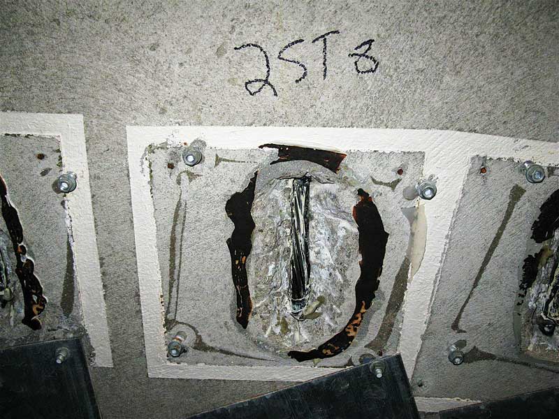
Small openings are made in the concrete slab to expose the post-tensioning strands (Figure 4). The openings are typically made at the slab/beam underside to limit the risk of moisture ingress following the evaluation. Where possible, the most likely location for strand deterioration is selected for review. For heat-sealed and stuffed systems, this is typically at mid-span of the bay, closest to the exterior slab edge. This area is a low point in the tendon profile where moisture that has entered the sheathing (typically through the live end anchor assembly) is most likely to accumulate and cause corrosion. For paper-wrapped or encapsulated systems, moisture does not travel along the sheathing, so locations of leaking cracks or control joints are often selected. Per PTI guidelines, openings should never be made near the anchorage zone, as there are highly-concentrated compressive stresses from the anchorages in these areas and disrupting concrete can result in the anchors rupturing through the slab. (Refer to PTI DC80.3-12/ICRI 320.6, “Guide for Evaluation and Repair of Unbonded Post-Tensioned Concrete Structures.”)
Prior to concrete removal, strands are located using ground-penetrating radar (GPR) or similar method. Once removals are complete, the sheathing is cut to expose about 200 mm (7.9 in.) of the post-tensioning strand. The strands are visually reviewed to document the condition of the steel, quantity and condition of protective grease, and the presence of moisture. However, one must be careful when interpreting these observations, as they are not necessarily representative of the post-tensioning condition beyond the extent of the opening.
The post-tensioning strands are qualitatively checked for tension using the penetration testing method. This involves attempting to insert a flathead screwdriver or similar tool between each of the six outer wires of the strand. If the wires can be penetrated, one or both of the wires is broken. Further, if all the wires can be penetrated, the strand is either under-stressed (i.e. carrying less tension than for which it was designed, due to either not being properly stressed at the time of construction or the strand having slipped at the anchorage) or fully de-stressed (i.e. broken or released from the anchorage). Determination of an under-stressed or fully de-stressed condition is based on engineering judgement and may require further quantitative testing to confirm.
Limitations of the penetration test method include:
- results are subjective to interpretation, based on the skill of the tester and the force they apply in an attempt to penetrate between wires;
- false results—for example, testing may not detect a tension deficiency if failure and test locations are far apart, as this distance could cause friction accumulation (either due to undulations in the tendon profile or possible corrosion product build up) to simulate tension in the strand, or corrosion product between wires can impede penetration; and
- cause or rate of failure cannot be determined.
Sign up for our weekly newsletter
Construction Canada weekly newsletters give the latest AEC industry news for those who build, design, engineer, specify, renovate or operate in the built environment.
Products & Services


Read the Latest Issue