
Glazing performance and sustainable design

By Mark Driedger
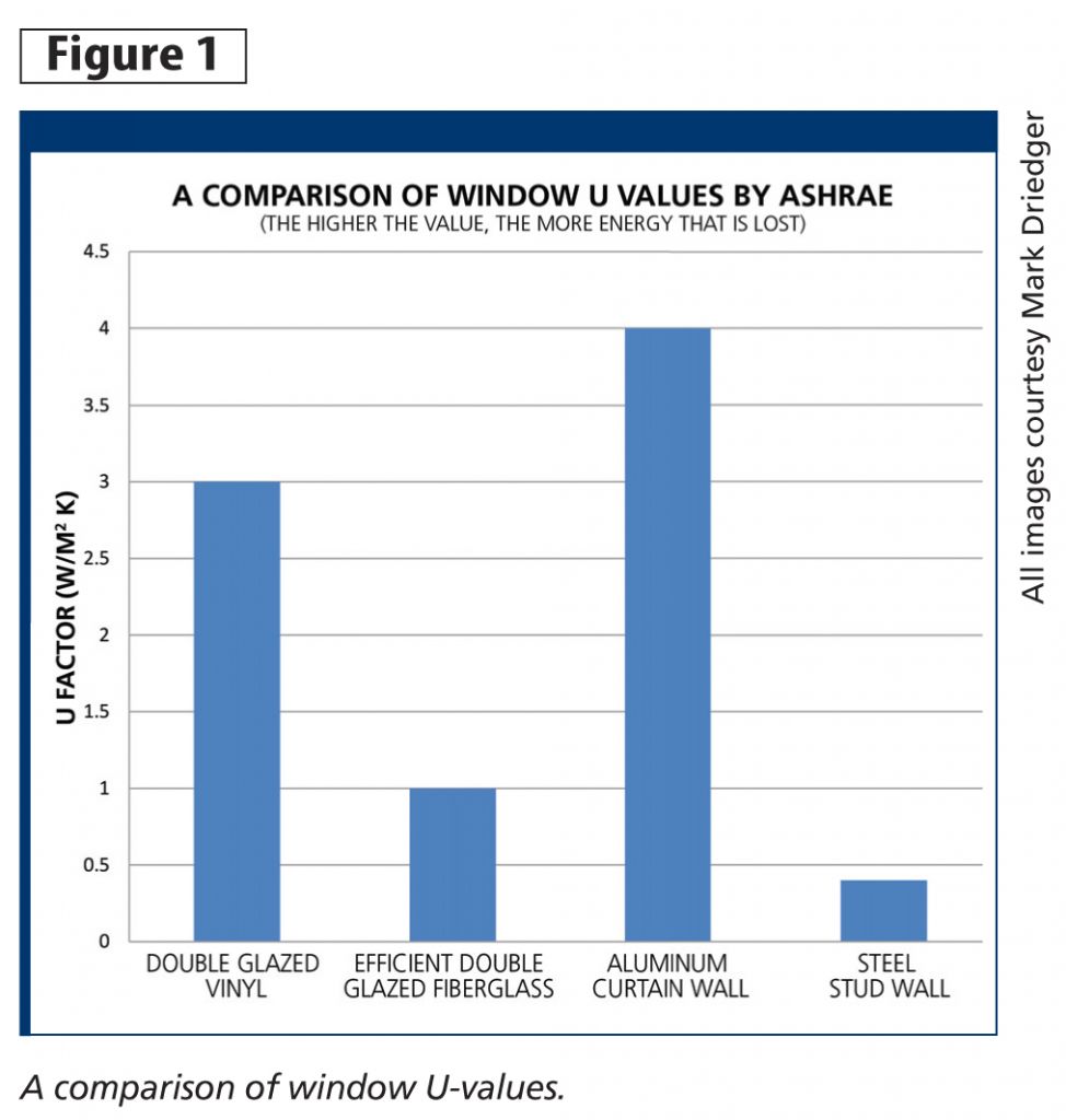
Glazing is an integral part of modern design. From a thermal standpoint, glazing and its structure or frame is the weakest point of a wall assembly.1 A double-glazed vinyl window with argon’s U-factor (i.e. thermal transmittance) is typically around 3 W/(m2 K). This means the window will gain or lose around 3 W per m2 per degree Celsius. An efficient fibreglass window system’s U-factor can be as low as 1 W/(m2 K). An aluminum curtain wall system can range as high as 4 W/(m2 K). On the other hand, the U-factor of a 152-mm (6-in.) steel stud, with batt and exterior continuous insulation, can be around 0.4 W/(m2 K).
These values can vary greatly depending on the assembly’s components. Figure 1 provides a comparison of typical values; it shows glazing is clearly not the best choice when savings on energy bills is the sole goal in a building’s design.
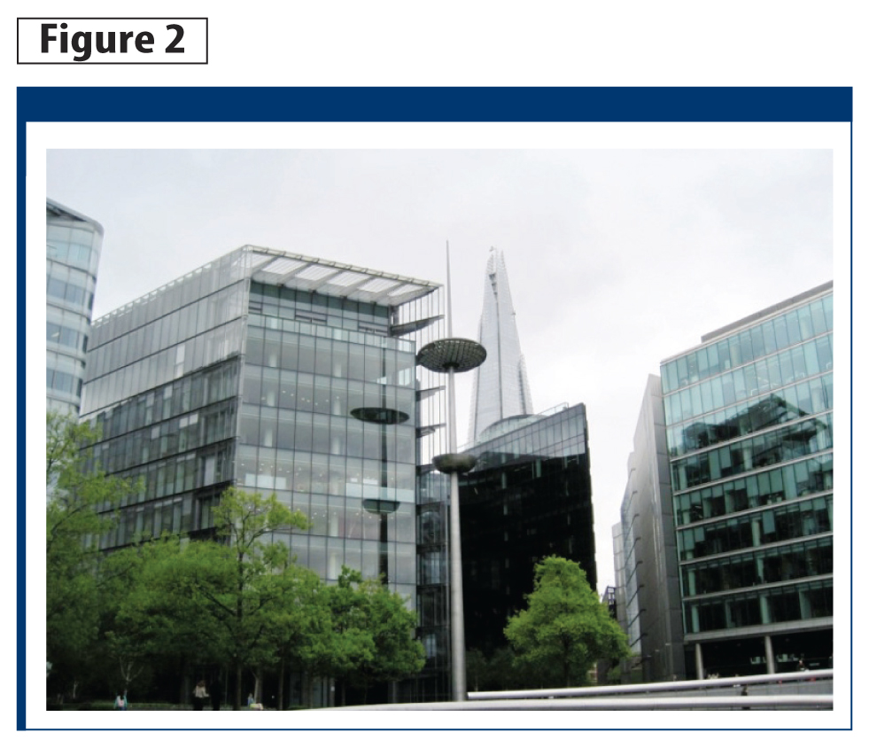
In today’s architectural landscape, clients and architects may neglect the energy issues and specify large expanses of glass in buildings. A snapshot of many major cities around the world, such as London, England (Figure 2), demonstrates designers have used glazed curtain walls as the primary assembly, putting the focus on construction simplicity, esthetics, and views over energy efficiency considerations.
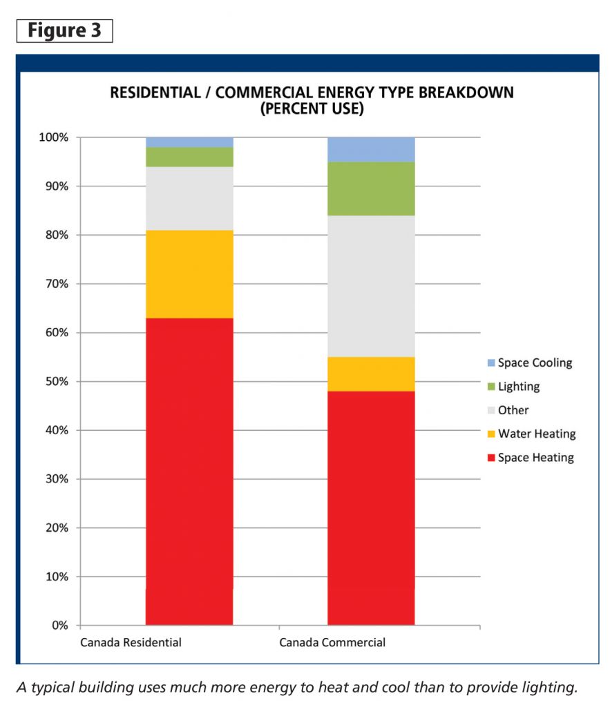
 Looking at data provided by National Resources Canada (NRCan) in Figure 3, it is evident the country as a whole uses more energy to heat and cool than to light a building. This means buildings would consume much less if they had reduced window area and more light fixtures.
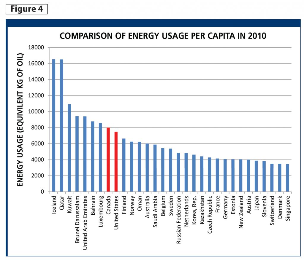
Energy loss through glazing is also increased when the building’s interior temperature varies greatly from the exterior building’s temperature. The more adverse the climate, the more important it is to have a well-insulated wall assembly with reduced glazing. This is partially why, as shown in Figure 4, Canada’s distinct four-season year ranks the country among the world’s highest per capita energy-consumers.
Many architects include ‘passive design’ as a sustainable asset in their buildings, with countless structures including large expanses of south glazing. Increased glazing and passive solar may be beneficial at warmer latitudes. In milder climates, the average daily temperature is closer to room temperature, reducing the amount of energy required to maintain a comfortable indoor environment. The sun’s warmth, which is typically more prevalent and intense at those latitudes, can be stored in thermal mass and used as supplement to heat at night.
In a colder climate, passive solar gains are limited because of the infrequent availability of direct sunlight and reduced intensity of sunlight during the winter. For example, in the Toronto area, buildings can go days without direct sunlight as a result of cloudy winters. Although there is some solar gain when the sun is available, this is lost quickly (and many times over) through the large glazing area during long, cold winter nights.
Without mechanical, movable insulation, windows are a net energy loss for a building in a cold climate. Therefore in a cold climate, adding windows for the sake of increased natural daylighting is not always a good strategy when saving energy is a design goal. Designers must be careful in the placement and use of glazing in buildings. Huge advances in window technology are required for a decrease in energy usage, while still using large areas of glazing in buildings.
 Using computation fluid dynamics to analyze window performance
Computational fluid dynamics (CFD) allow designers to recreate real world physics in a virtual system. Designers are now able to simulate the complex performance of assemblies, without complex laboratory testing.
Computer processing speed has evolved to a point where these complex, 3-D calculations can be completed on a home personal computer.2 Autodesk CFD, for example, integrates directly into Autodesk Revit, allowing architects to simply pull their building information models (BIM) straight into the program, to analyze 3-D energy flow.
Modelling a window assembly in different conditions
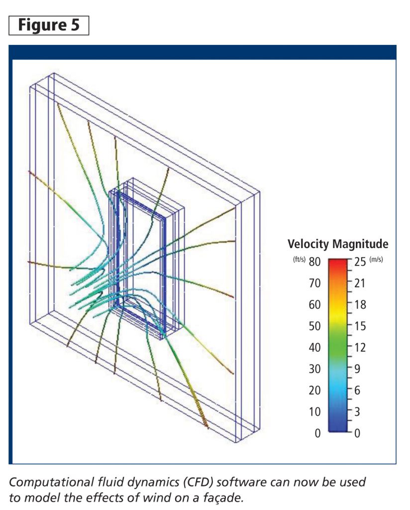
When the U-value of a window system is calculated using a window performance modelling software, such as Lawrence Berkeley National Library’s (LBNL’s) Window or Therm, it is sometimes done under still air conditions. These U-values are used to design the mechanical heating or cooling system for the building, replacing the energy losses of the windows and assemblies. However, it is important to understand how wind has an impact on windows. Wind chill not only affects exposed skin in the winter, but it also increases energy loss in buildings. Using Autodesk CFD, a window system can be modelled under different velocities of wind to measure the effect on the assembly (Figure 5).
Figure 6 shows a window assembly in a calm winter scenario. The wall modelled is an insulating concrete form (ICF) assembly and the opening modelled is a dual-glazed fibreglass window system shown in Figure 6.3 The interior of the assembly is 20 C (68 F) and is shown in red, and the exterior temperature is –20 C (–4 F) shown in blue.
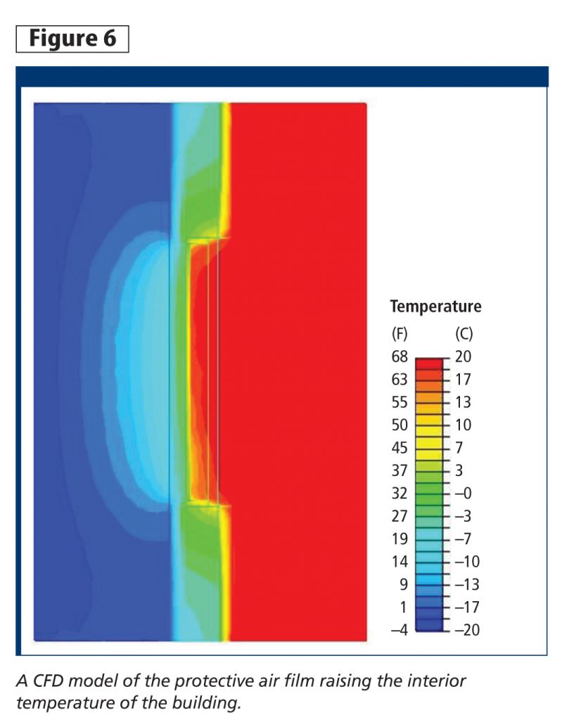
 The CFD model shows how a window effectively drops the insulating properties of the ICF wall by reducing the wall’s temperature immediately around the window’s connection to it. This is demonstrated by the green areas around the window opening in Figure 6. The cyan ‘plume’ of heated air can be seen on the exterior just outside the window opening. This ‘plume’ is actually a vital portion of the insulating properties of the window system. The heated column of exterior air, although producing a heat loss for the building, increases the temperature of the interior glass pane to a temperature of around 10 C (50 F), reducing surface heat transfer from the interior. A stable surface film, such as this ‘plume,’ is important to any thermal resistor with a low resistance value—for example, a window system or any assembly with little insulation.4
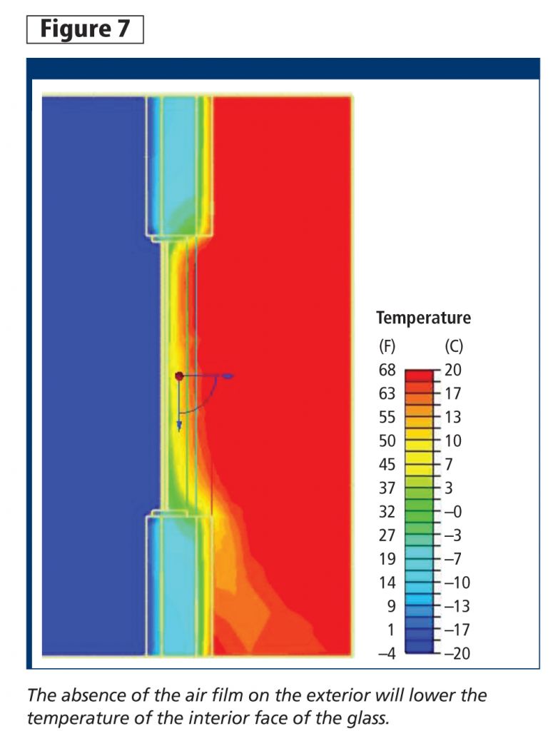
Figure 7 shows the same window system under a 10-m/s (22-mph) wind. The wind is directed perpendicular to the face of the glazing. The interior of the assembly is at 20 C and is shown in red. The exterior temperature is –20 C (–4 F) and shown in blue. In windy conditions, the protective plume of air on the exterior is eliminated, removing a large portion of the window’s insulating factor. The result is a reduction of the interior window temperature to approximately 2 C (36 F). The reduced surface temperature of the window increases the surface heat transfer with the interior causing a downward draft toward the building’s interior, which can be seen in the model.
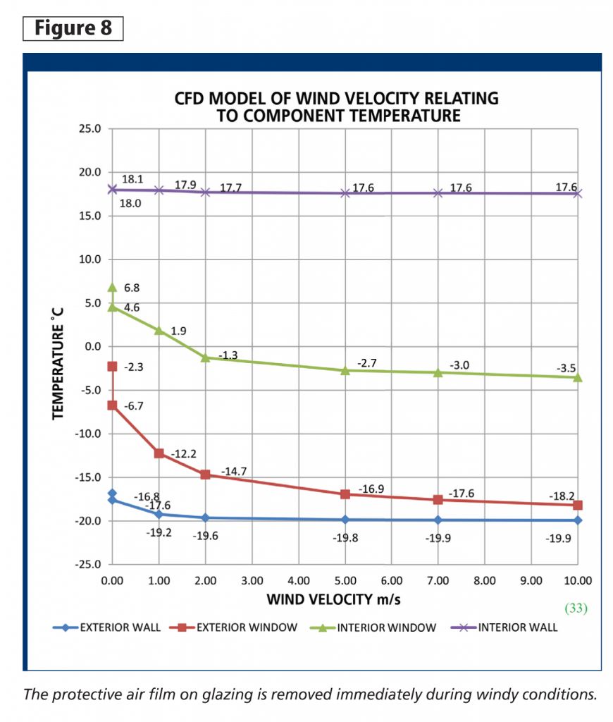 At what velocity is the exterior surface film reduced?
As seen in Figure 8, the temperature of the interior face of glass immediately drops as the exterior wind velocity is increased. The temperature eventually levels off, showing a reverse exponential relationship between wind velocity and temperature. The wall temperature change is not as pronounced, which indicates wind has a very small effect on well-insulated walls. However, the pressures associated with higher winds would have an effect if the construction’s quality was inferior. Improperly sealed window and wall assemblies would have increased air leakage in high wind situations, further decreasing the efficiency of the opening.
Therefore, Figure 8 suggests the insulating effect of the exterior air film is important to a window’s performance. It is rare to have a windless day, so the performance of windows most of the year is actually much less than advertised. Under a 2-m/s (4.5-mph) breeze on a –20 C (–4 F) day, the interior face of a window will drop to –2.7 C (27.1 F), as opposed to the 6.8 C (44.2 F) degrees when it is not windy outside.
What can be done differently?
In a cold climate, the overuse of glazing can be a rather short-sighted strategy. Although, present energy prices may support the practice, future ones may not. Either the energy performance of glazing needs to improve or less expensive energy supplies must be found for current designs to continue without prohibitive operating expense. The adoption of American Society of Heating, Refrigerating, and Air-conditioning Engineers (ASHRAE) 90.1, Energy Standard for Buildings Except Low-Rise Residential Buildings, by the Ontario Building Code (OBC) have moved in a positive direction by limiting glazing percentage. There are also other possible ways of dealing with this energy loss.
 Increasing the U-value of glazing is a logical way of reducing energy loss, although it is difficult to match the thermal properties of an opaque wall. The addition of surface films, increasing air spaces with additional panes, or changing the frame to low-conducting material have a positive effect on the overall U-value. However, it is important to note higher U-values in glazing are usually associated with lower visible light transmittance. Therefore, the higher the U-value, the darker the window. Energy losses through window framing is also typically higher than the losses through the glazing itself. Future assemblies consisting of low-conducting materials and vacuum panels will greatly reduce energy loss; however, technology must overcome the thermal bridging through the mullions.
Thermal mass and insulated shutters
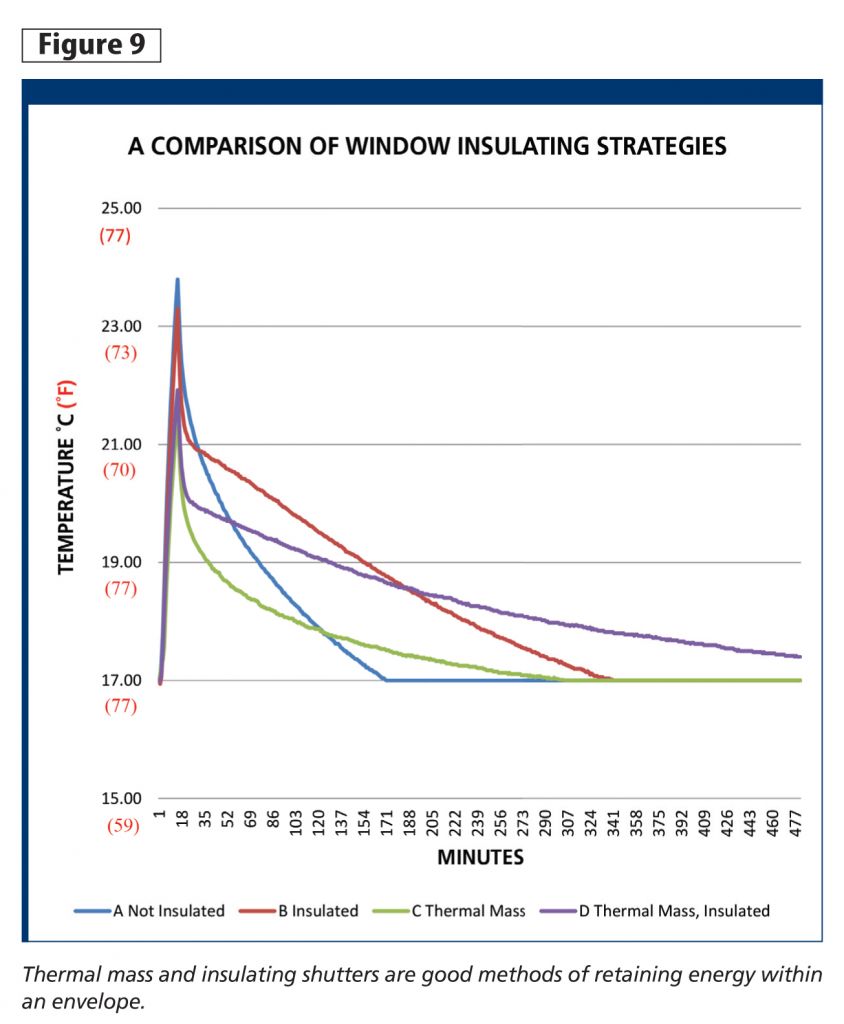
Increasing the thermal mass within the heated space also reduces energy loss. Figure 9 shows a simple experiment completed by this author’s firm, ATA Architects, where several temperature probes were used to measure how long an elevated temperature was maintained within an insulated box with a window at one side. The box was heated for 15 minutes, and then observed to see how long the temperature was maintained within the box.
The following tests were done:
- Test A–just glazing;
- Test B–glazing covered with an insulated shutter;
- Test C–glazing with a brick thermal mass; and
- Test D–glazing covered with an insulated shutter and a brick thermal mass.
As shown in Figure 9, Test D with the insulated shutter and the thermal mass held the energy within the box the longest. Test B, with the insulated shutter, performed the next best, followed by the thermal mass. The addition of thermal mass to the building and insulating shutters would be great options at reducing energy loss through glazing.
C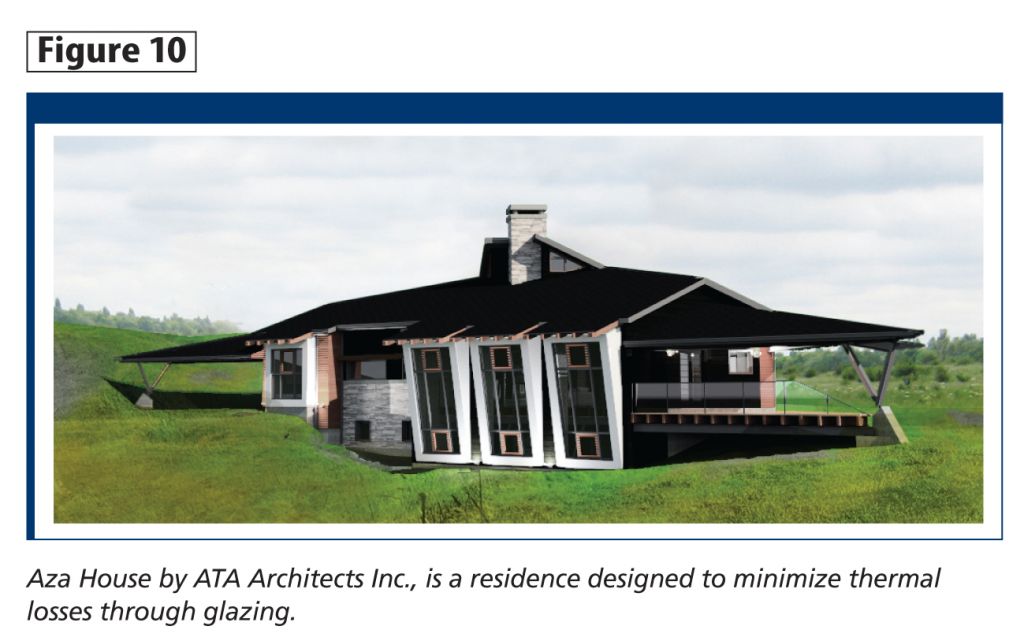 urrently, ATA Architects is working with Ramani Ramakrishanan and the building science studio at Toronto’s Ryerson University to develop a removable insulation system for aluminum curtain wall buildings. The studio is assisting and testing a system that can be theoretically added to the mullions and glazing to reduce energy loss in cold climates. An automated insulating shutter providing natural light when required while boosting the U-value of the assembly when natural light is not required would greatly reduce energy usage. The capital set aside for expensive high U-value glazing and thermally broken mullions could be exchanged for a mechanical insulated shutter system that covers a simple, cost-effective window system.
ATA Architects is completing a dwelling in Smithville, Ont., designed to counteract the weaknesses of glazing (Figure 10). Through the use of fluid mechanics software, and a wind tunnel at the Building Science Lab at Ryerson University, the house was designed to be aerodynamic, reducing energy loss associated with friction with the wind. Windows have been minimized along energy losing facades, and concentrated in protected areas. Drop-down insulating screens provide additional protection during the high loss months. Along with several other energy saving storage systems and strategies, the house is a study on how architects will inform design in the next decade in cold climates. The house is expected to be completed this summer.
Conclusion
Although the performance of glazing may not be ideal for cold climates, transparent glass surfaces remain vitally important to our health. Glazing provides a visual connection to the outside.
Nevertheless, architects and designers have to move beyond solely focusing on the visual appeal of glazing and start considering the lifecycle costs. Large glazed façades should not be marketed as a sustainable building practice in a cold climate. Glazing can be thoughtfully placed, and strategies can be put into place to minimize their losses.
Notes
1 For more, see N.B. Hutcheon and G.O. Handegord’s, Building Science for a Cold Climate. (back to top)
2 Visit oee.nrcan.gc.ca/publications/statistics/trends09/chapter3.cfm?attr=0. (back to top)
3 For more, see American Society of Heating, Refrigerating, and Air-conditioning Engineers’ ASHRAE 2013 Fundamentals Handbook. (back to top)
4 See note 1. (back to top)
 Mark Driedger is a sustainable designer, intern architect, and associate at ATA Architects Inc. He received his masters of architecture from Lawrence Technological University. Driedger is LEED AP and continues to integrate science with design and be contacted via e-mail at mark@ataarchitectsinc.com.
Sign up for our weekly newsletter
Construction Canada weekly newsletters give the latest AEC industry news for those who build, design, engineer, specify, renovate or operate in the built environment.
Related Products & Services


Read the Latest Issue
