Getting to the bottom of moisture management
By John H. Koester
Both gravity and temperature can create misunderstandings resulting in improper or inadequate moisture management design for the exterior building envelope.
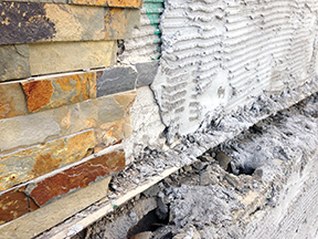
The lowest point of a building envelope is the wettest because of gravity’s influence (Figure 1). The low point of a building’s exterior wall system does not necessarily have to be the top of the footing (Figure 2) or the top of the stem wall (Figure 3). A low point in an exterior building envelope is a location that stops or slows moisture in liquid form from proceeding in a gravity-induced downward direction. Sometimes, this is intentionally done with a designed flashing system; often, it is the result of other components of the exterior building envelope system coming together to stop or slow the downward path of liquid water (Figure 4 and Figure 5).
When the highest point is wettest, it is due to temperature’s influence. Construction professionals can understand why a low point of a construction detail would be the wettest, but how could this be true for a high point/the top of a wall system?
When looking at the top of a wall where it meets the ceiling, a water pattern on the interior finished surface of the exterior wall may also be seen. The most obvious conclusion is there is a leak, a source of liquid water coming down and inside from a higher point. In most cases, this is exactly what is happening. However, there may be numerous other scenarios that could explain water and water patterns at a high point of an exterior wall detail.
One such scenario is water in vapour form will move upward with warm air to a higher point of a construction detail and come in contact with air or a surface cool enough to be a dewpoint and condense into liquid water and wet a construction detail (Figure 6). This can happen on exterior or interior surfaces of a construction detail (Figure 7). The other part of the answer has to do with why a high point of a wall would be cool enough to be a dewpoint when hot air rises and the top of the wall and ceilings should be the warmer.
This phenomenon is usually the result of a thermal bridge from the cold exterior of an exterior building envelope to a warm interior of an exterior building envelope with enough intensity to overcome the interior ambient air temperature’s ability to warm the construction detail (Figure 6 and Figure 7). The elements required to allow this are an opening to allow a sufficient amount of cool air to pass into or through the construction detail at this point, or a conducting material—such as steel, glass, solid concrete, or water—that can transfer this difference in temperature. Wet construction materials are good conductors of temperature and poor insulators; even the best insulations perform extremely poorly once wet.
So when a wet pattern in a high point of a construction detail is contributing to condensation, there may be an associated water source or wet material that has promoted cold temperature transfer—in other words, a water source that causes a temperature transfer and a dewpoint and a condensation wetting pattern, but is not actually leaking or absorbing into a construction detail to wet it (Figure 6 and Figure 7).
Another mechanism that transports moisture in liquid form into and through construction details is absorption. The general rule/law of physics says moisture will usually move from a high concentration of water into and through materials to a lesser concentration of water (drier materials) in an attempt to equalize the concentration of water. The distances this moisture travels can be surprising (Figure 8).
If certain conditions exist—such as the continuous source of liquid moisture, absence of driving mechanism and construction materials that funnel and or encapsulate (two or more) vapour retarders in the same exterior building envelope—the travel distance can be great. These distances will be proportionally expanded with the volume of the liquid moisture source. A large volume of liquid water has greater weight (i.e. pull of gravity) propelling the liquid moisture into and through construction materials.
The specified slider id does not exist.
Designing an exterior building envelope moisture management system brings a number of important factors into consideration:
- the potential amounts of moisture to be managed;
- how often the construction detail is exposed to this amount of moisture;
- exposure duration; and
- moisture’s physical form (i.e. liquid, solid, or gas).
Drainage is the movement of moisture from one point where it is not desired to a preferred location. In most cases, this is from a high point in a construction detail (or on its surface) to a lower point out of or off of that construction detail.
The moisture that may enter the exterior building envelope must be provided with a designed passageway to move it from a high point of entry to a lower one, and allow it to exit the exterior building envelope. The technology allowing liquid moisture to move downward in the interior of an exterior building envelope is a core, cavity, or a rainscreen drainage plane material. The processes stopping the downward movement of liquid moisture is a waterproof flashing material. The technology giving liquid moisture a reason to go in one direction or another is slope-to-drain/elevation variation, or high to low. The tools creating the opening from the wall’s interior to the exterior of the veneer/rainscreen material (brick, stone, or stucco) is the weep (Figure 9).
These four components are absolutely critical for an exterior building moisture management system to work. Weeps do not work until the liquid moisture gets to them. When moisture attempting to move downward in a core, cavity, or rainscreen is obstructed or slowed, it may just absorb into adjoining construction material and/or deeper into the exterior building envelope. If and when the liquid moisture gets to a flashing/water stop, if there is not any slope-to-drain to the exterior of the exterior building envelope, it may just accumulate and absorb into the adjoining construction material or find its way deeper into the exterior building envelope through a void in imperfect flashing or out through veneer material through an undesigned pathway. If the weep holes are not at the lowest point of the core, cavity, or rainscreen drainage plane, liquid water may accumulate and find its way deeper into the exterior building envelope or through veneer materials through an undesigned pathway.
All these consequences of an improperly designed moisture management system are potentially serious and may result in exterior building envelope component failure or total system failure, up to and including structural failure. An exterior building envelope moisture management system’s reliance on all system components to function in concert with each other cannot be stressed enough.
The last and lowest components are in many cases the least understood and prioritized—these are the weeps and weep screeds (Figure 10 and Figure 11). In the case of weeps, the materials, amount, and location is completely without reason. Materials often used are thought to wick water out of a core or cavity. However, this author advises not to get into a wicking contest with masonry materials. A weep of any kind, good or bad, every 1219 mm (48 in.) is of little value; as are weeps not at the lowest point of a core or cavity at the top surface of the flashing or water stop. A weep creating a hole in a veneer from the interior of the core or cavity to the exterior of the veneer is just another hole in the veneer that may let liquid moisture into the wall as well as let it out of the wall if there is no slope-to-drain.
Weep screeds have similar moisture management responsibilities, but in many cases they do not function appropriately. The notion a shrinkage crack between the metal and cementitious material (i.e. scratch coat, brown coat, and bedding and grouting mortar) is a dependable moisture management detail is ludicrous (Figure 12). However, for many commonly installed weep screeds, this is what the product literature says. The holes in the bottom are primarily ‘keying mechanisms.’ The holes for weeping will come when the stucco shrinks away from the metal ‘V’ stop.
A weep and weep screed must have compatible moisture moving capacity with the core, cavity, or rainscreen drainage plane above. If not, the slowing of moisture movement will cause an accumulative effect with all the negative consequences.
What makes a good weep?
There are specific criteria to follow when choosing weep technology. Masonry Design and Detailing defines weep holes as: “Openings placed in mortar joints of facing material at the level of the flashing to permit the escape of moisture.” The voids/tunnels and channels a weep creates through the bed joint of mortar, scratch coat, or adhering mortar must be at the lowest point of a core, cavity, or rainscreen drainage plane (i.e. where the water is) and must be no further than 305 mm (12 in.) apart (Figure 13). There is no need to consider modular configuration of masonry units because the voids/tunnels and channels are in the bottom side of the bed joint of mortar and do not affect layout or coursing.
A weep screed is a building material used along the base of an exterior stucco wall. It serves as a vent so moisture can escape the stucco wall finish above the foundation. It is a device used to terminate the bottom of a cementitious-based thin veneer rainscreen. This device should allow liquid moisture that drains down the back side of a thin veneer rainscreen and on the surface of the weather-resistant barrier in the rainscreen drainage plane to freely exit the thin veneer 38 to 51 mm (1.5 to 2 in.) below the bottom of the framed wall system and the top of the stem wall. For projects in the United States, the International Building Code (IBC) 2012 Section 2512.1.2, Weep Screeds, states:
A minimum [0.5 mm] 0.019-in. (No. 26 galvanized sheet gage), corrosion-resistant weep screed, or plastic seep screed, with a minimum vertical attachment flange of [89 mm] 3.5 in. shall be provided at or below the foundation plate line on exterior stud walls in accordance with ASTM C926, Standard Specification for Application of Portland Cement-based Plaster. The weep screed shall be placed a minimum of [102 mm] 4 in. above the earth or [51 mm] 2 in. above paved areas and shall be of a type that will allow trapped water to drain to the exterior of the building.The weather-resistant barrier shall lap the attachment flange. The exterior lath shall cover and terminate on the attachment flange of the weep screed (Figure 14).
It is critical the drainage/weep holes be numerous and not more than approximately 25 mm (1 in.) apart and located at the bottom of the weep screed and against the 89 mm (3.5 in.) back flange to allow for direct contact with the bottom of the rainscreen drainage plane. This is important for two reasons—the liquid moisture that drains down the rainscreen drainage plane will have an immediate exit point and the cementitious materials used to create the thin veneer will not have access to block them. (See Figures 15 and 16.)
Conclusion
Moisture will enter the building envelope and will need to be drained. This has become more and more the accepted practice, and in many cases, it is code-mandated. Unfortunately, the liquid moisture gets drained to the bottom of the wall with little thought given as to how it will get out. This article has presented pragmatic solutions to getting the moisture out at the bottom.
The specified slider id does not exist.
 John Koester is the founder and CEO of Masonry Technology Inc. With construction experience dating back almost 40 years, he has been a card-carrying mason and cement-finisher; for many years, he operated his own masonry construction business in the Minneapolis-St. Paul, Minn., area. Koester has extensive background in waterproofing systems in the areas of forensics, design, and installation oversight—both in restoration and complete re-roofing projects. He can be contacted via e-mail at john@mtidry.com.
Sign up for our weekly newsletter
Construction Canada weekly newsletters give the latest AEC industry news for those who build, design, engineer, specify, renovate or operate in the built environment.
Products & Services


Read the Latest Issue