Four ways to eliminate joints in wide-slab concrete floors
Shrinkage-compensating concrete
Ordinary concrete starts shrinking as soon as it is placed, and continues shrinking for a long time. The shrinkage puts the concrete into tension, causing cracks. Shrinkage-compensating concrete behaves differently. It starts out by expanding, putting the concrete into compression. After a few days the expansion ends and the concrete starts shrinking. However, the shrinkage does not put the concrete into tension—at least not right away; rather it just reduces the compression. If expansion and shrinkage are evenly matched, the concrete never goes into tension and does not crack.
The expansion comes either from expansive cement that replaces the portland cement found on ordinary concrete, or from an expansive component used with normal portland cement. ACI 223R-10, Guide for the Use of Shrinkage-Compensating Concrete, recognizes three kinds of expansive cement and four kinds of components, but not all are in regular use in Canada.
Expansive cement has become rare. Most shrinkage-compensating concrete in the country is made with an expansive component—Types K, S, or G. This work is mostly performed by specialist contractors, each of whom has their own favourite material. Fortunately, all the types produce similar effects.
To control cracks, the initial expansion must be restrained so the concrete goes into compression. Some restraint comes from subslab friction and other building elements, but the main source in most designs is conventional steel reinforcement. ACI 223 recommends rebar or wire mesh in two directions, equal to 0.15 per cent of the slab’s cross-sectional area. Some designers use less, however.
Floors made of shrinkage-compensating concrete require some special details if they are to remain crack-free. It is widely—though not universally—accepted the slabs should be roughly square, with an aspect ratio not greater than 3:1. Slabs must be isolated from walls and columns. The placing sequence needs to be carefully planned so each slab is free to expand.
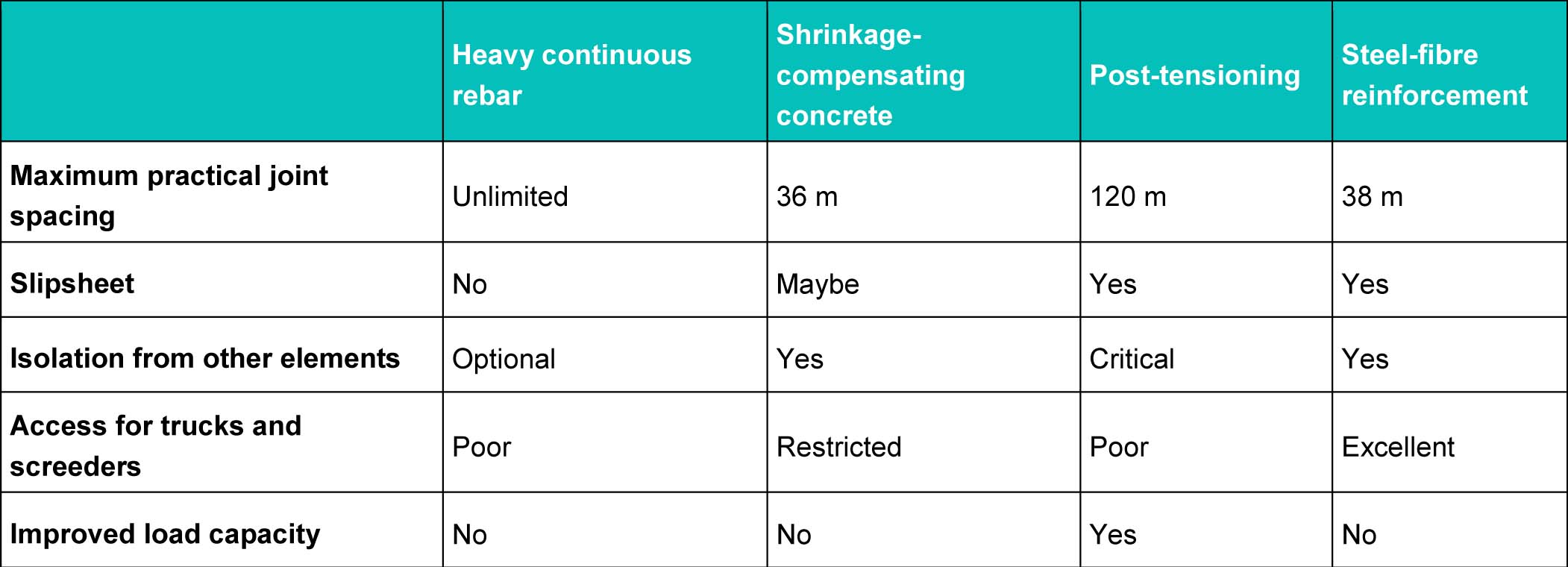
Shrinkage-compensating concrete routinely allows joint spacings of 36 m (118 ft). It is unclear where the upper limit lies. ACI 223 reports slabs as big as 1850 m2 (19,913 sf), which, if square, would result in a joint spacing of 43 m (141 ft). However, in normal practice, spacings over 36 m are rare.
More than any other method of wide-slab construction, use of shrinkage-compensating concrete requires special knowledge and attention to detail.
Post-tensioning
Shrinkage-compensating concrete puts slabs into compression using chemical action. Post-tensioning does the same thing, but with steel cables instead of chemicals.
The cables run the full length and width of the slab, encased in plastic or metal tubes. After the concrete has set, but before it has had much time to shrink, the cables are stretched and locked off at each end, putting the slab in compression. The steel used is much stronger than normal rebar, with a tensile strength of 1830 MPa (270,000 psi). The size and spacing of the cables depends on slab thickness and length, subslab friction, and how much compression is desired. Where the sole purpose of the post-tensioning is to prevent cracks, the design normally provides for mid-slab compressive stress of at least 350 kPa (50 psi). Some designers specify higher values, either to raise the safety factor or to increase the slab’s structural strength. Design information, including the formula used to determine cable size and spacing, is available in the Post-Tensioning Institute’s (PTI’s) book, Design of Post-Tensioned Slabs-on-Ground.
Though short slabs, up to 15 m (50 ft) long, are tensioned in one application, wide-slab construction usually involves a two-step process to head off early cracking. The first step involves applying one-third of the full design stress as soon as the concrete’s compressive strength reaches 8 MPa (1200 psi). The second step is to apply full stress after the concrete’s compressive strength exceeds 21 MPa (3000 psi).
As with shrinkage-compensating concrete, post-tensioning requires some special details. Slabs must be free to move horizontally, and be isolated from walls, columns, and any other sources of restraint. A plastic slipsheet is essential to reduce friction between the slab and sub-base. Some designers even use two sheets of plastic to further reduce friction. Slab ends must be accessible for stretching the cables—this sometimes requires narrow gaps between slabs to be filled after stressing has been completed.
Post-tensioning has been used in slabs up to 183 m (600 ft) long, but a more practical limit is 120 m (400 ft), which still exceeds the limits imposed by shrinkage-compensating concrete or steel fibres. However, post-tensioning differs from the other methods because the cost increases with joint spacing—a longer slab needs additional or bigger cables. Sometimes the joint spacing is limited not by engineering rules, but rather the project budget.
This method offers a potential benefit not available from any other method of wide-slab construction. Post-tensioned slabs can be made thinner while supporting the same loads, thanks to the prestress provided by the cables. The compressive stress induced by post-tensioning cables has the effect of increasing the concrete’s flexural strength. Structural engineers can take advantage of this when calculating slab thickness. For slabs supporting heavy loads, post-tensioning often allows a reduction in slab thickness of 25 to 50 mm (1 to 2 in.). There is less benefit when loads are light.
Post-tensioning has two important drawbacks, both of which centre on the need to keep cables in place. The first involves access during the concrete pour. Cables need to be chaired up in their final position as concrete is placed around them. This makes it hard to discharge concrete directly from ready-mix trucks and it interferes with modern screeding machines. Floors made with continuous heavy rebar and shrinkage-compensating concrete also suffer from this drawback, since both require mats of reinforcing steel in the pour. However, the issue looms larger with post-tensioning because it is so important to keep the cables positioned correctly. In Australia, where post-tensioning is more common, contractors use special ramps to support a screeding machine above the cables.
The second drawback is unique to post-tensioning. Cables should not be disturbed after they have been tensioned. Users must be careful drilling holes in the finished floor. Certain kinds of floor repairs become harder, and floor demolition is complicated—though not impossible.
Steel-fibre reinforcement
Steel fibres are short, thin pieces of steel added to the concrete mix. They range in length from 12 to 60 mm (½ to 2 3/8 in.). When added in sufficient numbers, they prevent visible cracks by stopping invisible microcracks before they spread. In wide-slab construction, the fibre dose is typically about 40 kg/m3 (67 lb/cy). The method comes from Europe, where it has been popular for years.
As with post-tensioning, wide-slab floors made with steel fibres should be laid over a plastic slipsheet and be isolated from other building elements. Some designers believe it is important to specify a limit to the concrete’s drying shrinkage. A specified maximum of 0.035 per cent at 28 days, with testing to ASTM C157, Standard Test Method for Length Change of Hardened Hydraulic–Cement, Mortar, and Concrete, is typical.
Steel fibres allow joint spacings up to 38 m (125 ft), which is about the same as shrinkage-compensating concrete. However, the fibres allow bigger placements because some of the joints can be sawn. It is possible, for example, to place a rectangle 38 by 76 m (125 to 249 ft) and saw it at mid-length, creating two square slabs. With shrinkage-compensating concrete, every joint must be a construction joint. This means joint spacing dictates pour size.
The steel fibre method offers one large advantage over the other three methods because it does not get in the way of concrete trucks and screeding machines. Since the fibres arrive with the concrete, the area of the pour is left wide open. In contrast, the other methods require steel reinforcement or post-tensioning cables throughout the slab, restricting access.
The only serious drawback reported with steel fibres is the appearance of fibres at the floor surface. To hide the fibres, some designers call for a dry-shake finish. The use of shorter fibres, about 25 mm (1 in.) long, along with some care in floating and trowelling the concrete, keeps exposed fibres down to a low number. Most users find this acceptable.
One- and two-way wide-slab construction
Most wide-slab floors have extended joint spacings in two directions. However, continuous heavy rebar and post-tensioning offer another option—a one-way floor with a wide-slab design in one direction, and a conventional jointed design in the other. This is common in very narrow aisle (VNA) warehouses that have superflat floors laid in long narrow strips (Figure 4). Each strip supports a single warehouse aisle, and the construction joints between the strips fall under the storage racks. The reinforcing bars or post-tensioning cables run only in the down-aisle direction.
Common ground
Though each method of wide-slab construction has its own benefits and drawbacks, all share certain features.
Any wide-slab floor will be more costly to build than an unreinforced floor full of joints. This inescapable fact is occasionally enough to make designers and owners reject all the methods described here. However, a full accounting must consider more than construction costs. After allowing for joint filling, and for joint maintenance over the building’s lifespan, a wide-slab floor may be cheaper than the conventional alternative. Additional benefits are harder to quantify, but are no less real. They include:
- reduced wear and tear on forklift trucks;
- better floor flatness (because there are fewer joints at which the floor can curl); and
- less downtime for joint repairs.
In general, the harder a floor is used, the easier it is to justify wide-slab construction.
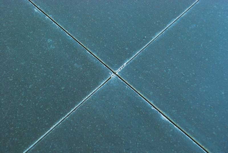
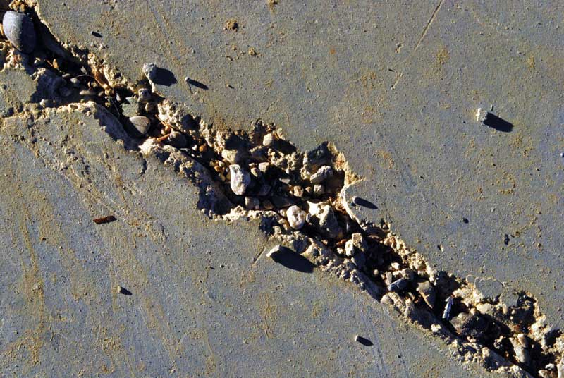
Another consideration shared by all wide-slab methods is the likelihood of wide joints. This is a trade-off. When the number of joints is greatly reduced, the few joints left have more to do. Given the same amount of concrete shrinkage or thermal contraction, joints 30 m (98 ft) apart are going to open wider than those 3 m (10 ft) apart. (Perhaps not 10 times as wide, but wider.) For this reason, many wide-slab designs include armoured joints (Figure 5).
When looking at an industrial concrete floor with closely spaced joints, it is clear the floor would look better, do its job better, and last longer, if it had 1/8 or 1/10 as many joints.
The specified slider does not exist.
 George Garber is the author of Design and Construction of Concrete Floors, Concrete Flatwork and Paving with Pervious Concrete. Based in Lexington, Kentucky, he consults on the design, construction, and repair of concrete floors. Garber can be reached by e-mail at ggarber@iglou.com.
Sign up for our weekly newsletter
Construction Canada weekly newsletters give the latest AEC industry news for those who build, design, engineer, specify, renovate or operate in the built environment.
Products & Services


Read the Latest Issue