Floor vibration control strategies for adaptive reuse of buildings into labs
This viability was demonstrated by successful implementation of a TMD solution during the design of a new multi-storey laboratory building. The performance objective was vibration Class A in all labs. A total of 166 TMDs were installed throughout the building, with 100 per cent of the labs achieving Class A, and approximately half the labs achieving the more stringent Class B. Equally important to the performance was the cost savings on steel framing: approximately $5 million USD.
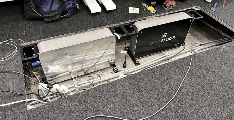
Active mass dampers (AMDs) are a recently developed active vibration control device that addresses some of the shortcomings with TMDs. TMDs control a single mode of vibration of the floor, must be spatially located at the point of maximum deflection, are typically heavy (upward of 2,000 kg [4,409 lbs]), and require structural connections to the floor. Whereas AMDs can control motions over a wide frequency range (thus addressing multiple modes of floor vibration), they can be located away from peak deflection points, and are very light (67 kg [147 lbs]).
Unlike TMDs, AMDs require power and internet connectivity for operation and maintenance access. However, the current draw is very low (equivalent to a laptop), and a great amount of research has gone into developing a robust design that is essentially maintenance free. A key feature is that these devices are plug-and-play, with very little tuning required. Being light and compact, the devices can be easily installed to the web of a beam or anchored directly to the floor (top or bottom).
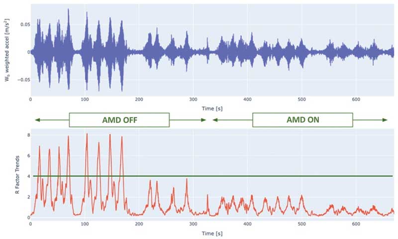
Example time traces from the AMD installation are shown in Figure 3 for both the “AMD off” and “AMD on” conditions. The top plot is the acceleration versus time trace, and the bottom plot is the response factor, which is defined as the multiple of the ISO base curve (i.e. R=4 indicates levels four times the ISO base curve level). A fourfold reduction in response factors is observed with the AMD on, going from R=8 (ISO–workshop) to R=2 (ISO–residential night).
The choice between TMD and AMD is generally project specific. By proper design, both technologies effectively reduce vibrations and, therefore, higher performance objectives can be attained. Response maps can be used in conjunction with TMD or AMD models to provide an understanding of where higher performance can be achieved. This can be very beneficial for adaptive reuse projects where combined structural-TMD/AMD solutions can be developed to optimize cost and performance.
Specifying vibration controls
When required, supplementary damping devices can be included in Division 10 – Specialties on building projects. These specifications are typically developed by the vibration engineer as they require specialized knowledge and information. While some solutions are offered “off the shelf,” many are customized for the project. As a minimum, the specification should include the following information:
- Design specifications for TMDs and AMDs.
- Number and locations of TMDs/AMDs.
- Total weight and anchorage forces for installation points, for each device.
- Access requirements for power, ethernet, maintenance, as appropriate.
- A list of qualified suppliers.
- Commissioning and performance verification test methodology and reporting requirements (factory and field, as appropriate).
- Submittals, such as shop drawings and performance verification test reports.
Sign up for our weekly newsletter
Construction Canada weekly newsletters give the latest AEC industry news for those who build, design, engineer, specify, renovate or operate in the built environment.
Products & Services


Read the Latest Issue