Five common mistakes made in the façade industry
This results in a grid of relative lighter gauge metal (18 ga). One of the principle mistakes made in substructure design and installation occurs at slab edges where the vertical hat bar is extended over traditional points of deflection. It is best to think of it this way. The superstructure is wrapped in a light-gauge steel cage and has traditional points of deflection. The 18-ga net is left to bear the energy/force of this deflection. The outcome is the substructure gets torn apart or buckles, and the façade skin cracks or bows. Vertical members within the substructure must stop and start at each floor slab and respect all other points of deflection in a building. They also require a gap between each other. This has been witnessed where lengths of vertical members—up to 8 m (25 ft) long—are stitched together with fasteners to climb the height of a building and cross over every floor slab. Too many times a lightweight façade skin will fall victim to this condition, crack or bow, and the skin material is assumed to be the issue. When cracks occur in masonry walls, one assumes the building settled or shifted, and the blame is directed toward the ‘settling of the structure,’ and not necessarily the masonry. Lightweight façade systems are also at the mercy of this settling, shifting, and deflection phenomenon, and can experience failure just like masonry. However, these are often characterized as a ‘material failures.’ Lightweight façade systems can manage the movement with ease when the proper principles are adopted and implemented.
Another item to consider is when vertical members have joints, a singular façade panel should never cross the gap when being fastened to separate vertical girts in succession. As the substructure expands, contracts, and responds to the points of deflection, girts move independently and not always in the same direction or at the same rate. The panel modules should stop and start as the vertical members supporting them do. This principle also applies to expansion joints, though specific superstructure expansion joints will require a detail for far greater movement. Horizontal members in the insulation plane cannot be continuous either. A gap should be present when these members stop and start in succession. While movement along the horizontal members is not as common, notwithstanding expansion and contraction, they need to respect these basic principles as well. Girts, regardless of their configuration (Z, hat, exterior/interior corner) can all be ordered in various sizes to suit the specific project, and this can be determined during the shop drawing phase.
As discussed in the previous section, the opportunity for expansion and contraction of all components in the façade system is always present and when married with the traditional points of deflection in a superstructure, the big picture is quite dynamic. Designing and assembling a high performance substructure is not difficult, but the outcome of a poorly designed and installed one is.
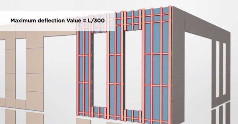
Mistake #4 – Poor deflection limit of substructure
In the author’s experience, the substructures for lightweight façade systems should be engineered for a deflection limit of L/300. Girts and panels expand and contract. The superstructure will exercise some deflection, and in some cases/places, take the substructure with it. However, the substructure should not be experiencing an out-of-plane deflection of more than L/300.
Typical façade skin materials, such as panels of porcelain, high-density fibre cement, phenolic, ceramic/terra cotta, promise great performance and longevity when designed and installed correctly. When a substructure has more deflection in out-of-plane conditions, it will place unnecessary stress on panels and the fastening system, resulting in panel cracking and distortion. For many Canadian scenarios, designing a substructure with 18-ga girt systems is a great start to achieving a limit of L/300. Spans between the members and the respective fastening points will play a large role in determining this deflection limit, but there are other key factors as well. For example, hat bars are being used for the vertical members directly behind the panels. These are sometimes called ‘omega’ channels. Hat bars, due to their shape, have higher deflection resistance than a Z bar of the same size and gauge.
Designing a substructure that suits the various products fastened to it and engineered to confront the dynamic conditions surrounding it of not only today, but tomorrow, will give the ‘frontline systems’ the advantage they require to deliver the required performance.
Mistake #5 – Inadequate shop drawings
Shop drawings are instructions for installation of a specific project. Instead of being specific and comprehensive, inadequate drawings merely show a few of the basic details of the project’s general conditions. An ideal shop drawing package will determine a successful path for installation. It will present a ‘system drawing’ that could be a few pages long depending on the project’s complexity, and illustrate the fundamental principles of fastener spacing, ventilation cavity in sections and plan view, and the substructure assembly for quick reference at any time during the façade installation. The shop drawings should also detail the fixed and floating points of fasteners (for exposed fastener conditions) as well as the components and placement of concealed fastener systems when applicable. An elevation view of substructure layout is also common. Concluding the shop drawings should be general notes that itemize in detail all the components that go into the façade assembly (fasteners, girts, membranes, panel manufacturer and makeup, etc.). The main body of the shop drawings will present elevation views of all applicable areas for installation of the façade and a comprehensive panel layout. Details in section view will be provided showing how the façade system assimilates with windows, flashings, adjacent materials, roof, exterior/interior corner conditions, horizontal/vertical joints between façade skin, and expansion joints in superstructure.
While the content of shop drawings is plentiful, and the time and effort to complete them is significant, the value is unquestionable. Everyone including designers, constructors, and end-users benefit from complete, high-quality shop drawings. The complexity of construction has increased in recent times to embrace more sophisticated assemblies with higher thermal performances to address the challenging effects of climate change. With this added complexity and the need for more resilient structures, it seems logical to eliminate the unnecessary variables (e.g. shop drawings) diminishing the quality of façades.
Conclusion
Mistakes cost money is the old adage. In this case, some of these issues are not unanimously outright mistakes, but oversights or honest ignorance of best practices. The good news is these issues are completely preventable and getting project teams on the high road of design is readily achievable.
Jeff Ker has more than eight years of technical sales experience in the Ontario architectural and design industry. His experience includes two years in the West Coast market and more than six years in the Eastern Canadian market, representing a variety of rear-ventilated rainscreen (RVRS) systems. Ker has a solid background in technical sales, project management, and liaison with the construction community. He can be reached via e-mail at jker@engineeredassemblies.com.
Sign up for our weekly newsletter
Construction Canada weekly newsletters give the latest AEC industry news for those who build, design, engineer, specify, renovate or operate in the built environment.
Related Products & Services

Read the Latest Issue