Façades for the future
Thermal performance
Beyond their obvious structural function, walls are important to the thermal performance of a building. Acknowledgement of this required the industry to change gears. Previously, the predominant school of thought said roofs were important. Buildings have become a focus for energy consumption—in fact, a building can lose up to 70 per cent of its energy through the façade, slab edges, and fenestration. (For more information, visit www.e-education.psu.edu/egee102/node/2070, or www.oaa.on.ca/oaamedia/documents/Thermal%20Bridging%20And%20Whole%20Building%20Energy%20Performance.pdf.) Hence, walls are important.
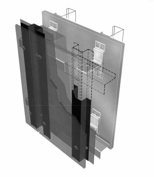
When insulation is installed into an RVRS or an outboard continuous insulated system, designers must consider heat bypasses. The façade must be set in a substructure and that substructure could conduct energy; thus, it could make the insulation less effective. The solution to this problem is thermally-broken substructures.
Design guides exist for thermally-broken substructures and how to specify the substructure for a high-performance façade system.
Consider the example of mineral wool in the context of a thermally-broken substructure and effective R-value. Mineral wool is noncombustible and does not have the highest performance in terms of thermal value but for this example assume that 127 mm (5 in.) of mineral wool will produce R21. What happens to that R21 value when we put it into an envelope? Does the performance value change because the envelope design introduces other conductive elements, such as substructures? Is the energy from the inside going to race out through a pathway? Will it be lost? Yes, in fact, it will.
An R-value table created by Morrison Hershfield looked at the idea of an outboard insulated façade. If the starting point is R21, the end result will be R11 to R15 when employing the “old ways.” R11 is only 55 per cent of R21; 45 per cent of the insulation value has been thrown away. We could produce a value of R15 with cross-girtting, but that is still only 70 per cent.
It is possible to achieve more with a thermally-broken substructure. If the builder employs this technique, the system should achieve around R19 to R21—a lot closer to the insulation value of the insulating material. (For more detail, see Engineered Assemblies’ SYSTEM2 design guide/TcLip.) All the components of the building envelope, put together in a system, contribute to the thermal performance. Various documents and data suggest every single component of the envelope is either neutral, takes away efficiency or provides efficiency. (For more information, see Linear and Point Transmittance Evaluation for Engineered Assemblies T-100 Cladding Attachment System, Oct 6/2016.)
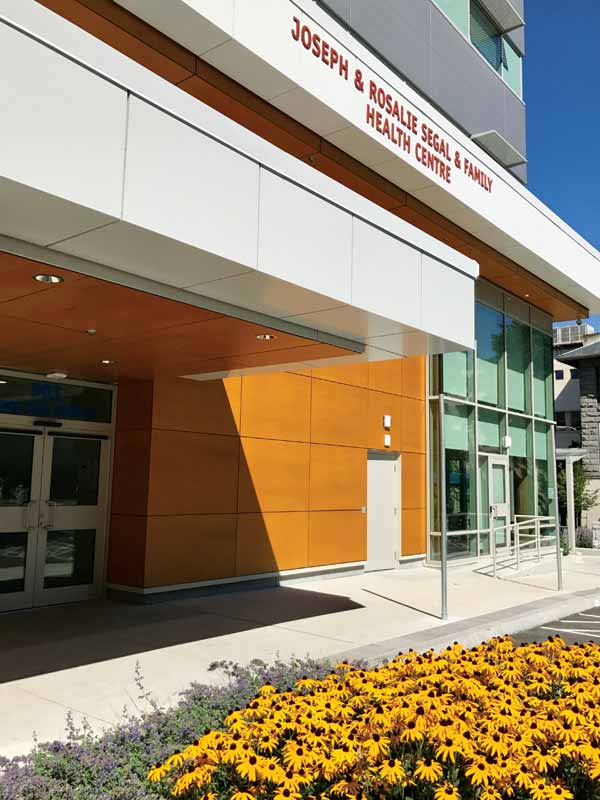
Photo © Richard Hazel
Vertical expansion and contraction
Extreme weather conditions affect the façade system. Expansion and contraction are more pronounced with lightweight, low-mass façade systems, especially when subjected to frequent, extreme weather changes. Heat waves, more transitions over the freeze/thaw line, and higher winds mean components are going to be moving.
Certain design guides can offer prescriptive ideas on how to create a façade system that can work within this dynamic environment.
A building face is a large area. Consider the example of a face measuring 30 x 30 m (100 x 100 ft). One cannot just cover that area with a big steel cage (i.e. a substructure). It would be like a big steel net trying to hold everything in place. There is too much movement in a building from expansion and contraction of the materials, as well as movement from the control joints. Ideally, one should stop and start the substructure at every floor slab. None of the vertical hat bars creating the 25-mm plenum should go over a floor slab, because it is point of deflection in a building. Horizontal z girts, in this example, should be about 3 m (10 ft) long. The gaps between the vertical hat bars and the horizontal z girts forming the grid for this sample RVRS system should be >/=3 mm (11.8 mils).
The “quadrants” created with the sample grid above will operate independently, allowing them to move and shift since all the pieces are going to expand and contract. Wind loads are higher on the corners of a building than they are in the centre of a facade, and therefore, the outside corners of this sample building will experience more natural forces. Due to the different forces acting on different parts of the building, it is not advisable to connect one system completely together. In a high-performing system, quadrants should be employed, and within quadrants, the system should address control joints.
Sign up for our weekly newsletter
Construction Canada weekly newsletters give the latest AEC industry news for those who build, design, engineer, specify, renovate or operate in the built environment.
Products & Services


Read the Latest Issue