Ensuring Energy Efficiency: Specifying windows and curtain walls for cold climates
by mdoyle | October 3, 2013 3:03 pm
 [1]
[1]By Steve Fronek, PE
In most parts of Canada, commercial building energy efficiency is significantly affected by conductive heat loss. In the winter, resistance to undesirable condensation on interior surfaces is important. New insulating glass and framing options are available to reduce heat loss and air leakage, control solar heat gain when appropriate, and minimize the potential for condensation.
However, understanding how to best specify materials for a particular project involves first knowing the basic principles of heat transfer, which occurs from objects of higher temperature to those of lower through conduction, convection, or radiation.
Conduction, convection, and radiation
Heat transfer through solid materials takes place via conduction. While aluminum is widely used as an engineering material because of its strength, light weight, and ability to accept durable finishes, it exhibits a high thermal conductance. This attribute makes an aluminum surface ‘cold’ to the touch, even when its surface is quite close to ambient air temperature, since heat quickly transfers from the skin to the aluminum.
In an aluminum window or curtain wall, the most common means of reducing conductive heat transfer through framing is by adding low-conductance ‘thermal break materials’ such as polyurethane, fibre-reinforced polyamide nylon, polyvinyl chloride (PVC), or flexible elastomers like silicone, neoprene, or ethylene propylene diene monomer (EPDM). All these thermal break materials exhibit unique design advantages and limitations.
Effective thermal barriers may be either structural (i.e. designed to resist wind loads and dead loads as an integral part of the extruded aluminum assembly) or non-structural (i.e. designed to be supported by fasteners or interlocks). The National Building Code of Canada (NBC) requires thermal breaks in metal window and curtain wall framing.
Non-conductive wood, cellulosic composite, vinyl, and fibreglass framing has each captured or retained significant market share in residential markets, but for the reasons mentioned, thermal barrier aluminum remains the material of choice for non-residential applications.
Heat transfer through fluids (either liquids or gases) takes place via convection. A change in medium from solid to gas, as occurs at a glass-to-air surface, has an inherent resistance to heat transfer. Convective heat transfer commonly is reduced by the addition of air spaces in insulating glass (IG) units. The U-factor of IG units can be further reduced by filling the between-glass spaces with lower-conductivity inert gases such as argon or krypton.
In framing areas, convective baffles or cavity fillers can be employed to impede convective heat flow, providing incremental improvement in U-factor.
Heat also can transfer in the absence of any intervening medium solely due to temperature difference between two objects. This radiation heat transfer depends not only on temperature difference, but also on ‘view factor’ (i.e. a measure of the amount two surfaces ‘face’ each other), as well as on the emissivity and absorptivity of the facing surfaces.
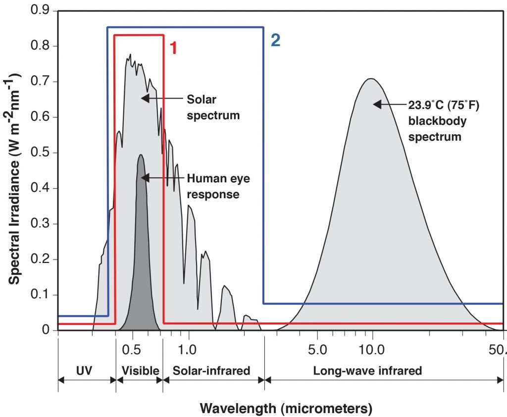
Low-emissivity (low-e) glass has an almost-invisibly thin coating—only Angstrom units (one ten-billionth of a metre) thick—that is reflective to long-wavelength infrared radiation, but transparent to shorter wavelength visible light. Both pyrolitic ‘hard-coat’ and sputtered ‘soft-coat’ low-e glass coatings are designed to reduce radiation heat transfer.
In framing areas, cavity fillers can be employed to impede radiation heat flow by reducing view factor between warm and cool surfaces.
 [2]
[2]Triple glazing
In response to increased stringency of model energy codes, as well as zero-carbon sustainability goals, many manufacturers’ curtain walls, fixed windows, and operable vents are now designed to accept triple glazing. Systems designed especially for triple glazing help achieve the low U-factors needed for the buildings of the future, without compromising esthetics and durability. Extended glazing pockets accept up to 50-mm (2-in.) glass thickness, and heavy architectural window (AW) Class hardware carries the added weight in casement, awning, and hopper vents.
Whether design calls for hermetically sealed triple-glazed IG units, or triple glazing with between-glass blinds for privacy and control of solar heat gain, modern systems can accommodate the most durable infill assemblies, orientation-tuned for maximum efficiency. Multiple-cavity low-conductivity argon gas fills and warm-edge spacers are available to further enhance performance.
Interior surface low-e
While not typically achieving thermal transmittance equal to triple-glazed IG units, the addition of an interior ‘fourth-surface’ pyrolitic hard-coat low-e coating on conventional double IG units sometimes represents a solid trade-off between cost, weight, and performance improvement. However, design/construction professionals should be aware that by lowering interior surface temperature, fourth-surface low-e coatings can adversely affect condensation resistance.
Suspended films
Suspended coated film (SCF) technology was first introduced to the architectural glazing market in in the early 1980s, before low-e glass coatings were readily available. Very low centre-of-glass U-factors can be achieved with SCF IG units without much added weight, which is especially important for the ease-of-operation of large double-hung or sliding windows.
Low-e-coated film reduces radiation heat transfer and, when tensioned, also sets up multiple cavities within the IG units, reducing convective heat transfer. Coated polyester films require great care in fabrication to avoid wrinkling and to help ensure IG unit longevity.
Solar heat gain co-efficient
Solar heat gain co-efficient (SHGC) is a measure of glass’ ability to block energy transmission across the solar spectrum from ultraviolet through visible wavelengths to infrared. Permanent shading projections reduce SHGC by using a simple multiplier based on a ‘projection factor’ equal to the horizontal shading depth divided by the window height.
In most new commercial buildings, even in cold climates, the design team is trying to maintain high visible light transmittance (VT) to connect occupants to the outside, provide views, and exploit natural daylighting, while minimizing summer solar heat gain for energy efficiency. It is important to remember much of the load placed on a building’s air-conditioning system comes from waste heat generated by artificial lighting. In conjunction with appropriate VT glass, photosensitive controllers can be used to turn off indoor lights when unnecessary.
Air infiltration
Air infiltration through windows and walls is important to total building energy performance, as it not only takes energy to heat or cool infiltrating air, but also may require latent energy to remove undesirable humidity during summer. Air infiltration performance usually is considered separately from other thermal performance characteristics. For consistency and comparability, standardized U-factors and SHGCs assume no air infiltration is present.
 [3]
[3]For the purposes of energy modelling, all new fenestration systems are usually assumed to perform comparably with respect to air infiltration. However, the same is not true when replacing old, leaky windows.
Based on the American Society of Heating, Refrigerating, and Air-conditioning Engineers’ ASHRAE Handbook of Fundamentals, air infiltration rates for various types of windows can be assumed to be:
- 0.5 l/s·m2 at 300 Pa (0.1 cfm/sf at 6.27 psf) for fixed windows or curtain wall;
- 0.5 l/s·m2 at 300 Pa (0.1 cfm/sf at 6.27 psf) for new AW Class operable windows;1[4]
- 12.5 l/s·m2 at 75 Pa (2.5 cfm/sf at 1.57 psf) for existing non-weatherstripped hung or sliding windows;
- 5.0 l/s·m2 at 75 Pa (1.0 cfm/sf at 1.57 psf) for existing weatherstripped hung or sliding windows or non-weatherstripped awning or casement windows; and
- 2.5 l/s·m2 at 75 Pa (0.5 cfm/sf at 1.57 psf) for existing weatherstripped awning or casement windows.
(Note: 0.5 l/s·m2 at 300 Pa (0.1 cfm/sf at 6.27 psf) is equivalent to 0.2 l/s·m2 at 75 Pa (0.04 cfm/sf at 1.57 psf.)
For calculating energy impacts of air infiltration, tested rates are adjusted for wind velocity at the window face. Site monthly day/night weather data includes both average wind velocity and direction. Only the windows on windward elevations exhibit air infiltration at any one time.
Uncontrolled air infiltration through cracks and voids in the building envelope increases building energy consumption. By putting untimely heating and cooling load into return air, and/or adversely affecting comfort and air quality in the conditioned space, uncontrolled infiltration creates HVAC load. Conversely, ‘controlled ventilation’ usually is defined as the regulated and relatively steady air supply necessary to maintain indoor air quality (IAQ), makeup for equipment exhaust, or balance exfiltration due to positive building pressure.
As long as the exterior average air temperatures for the period in question are known (from meteorological data), it is relatively easy to calculate the energy necessary to raise or lower infiltrating air to the targeted interior temperature. These are called ‘sensible’ energy expenditures.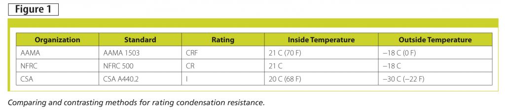 [5]
[5]
Hs = c·ρ·QW·(Tin – Tout) W (Btu/hr)
Where:
Hs = Sensible energy to raise/lower air from Tout to Tin in W (Btu/hr);
c = Specific heat of air ~ 512 J/kg·C (0.240 Btu/F·lb) at standard temperature and pressure (STP);
ρ = Standard density of air ~ 1.2 kg/m3 (0.075 lb/cf) at STP;
QW = Air infiltration adjusted for wind at the window face in L/s (cf/hr);
Tin = Interior ambient temperature target; and
Tout = Exterior ambient temperature.
Assuming humidity control is present in the building’s HVAC system, the energy necessary to dehumidify infiltrating air in the summer is called ‘latent’ energy expenditure, because of the need to overcome water’s latent heat of evaporation.
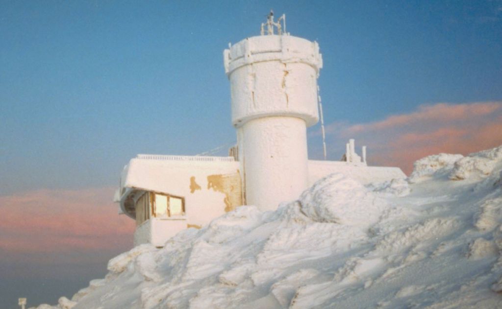 [6]
[6]“home of the world’s worst weather.” With conditions rivaling those of Antarctica, the high thermal performance, operable windows on the Summit Building maintain a comfortable interior in spite of the frigid outside climate. During the few nice days, the windows can be opened for fresh air and natural ventilation. Photo courtesy Wausau Window and Wall Systems
HL = L·ρ·QW· (Win – Wout) W (Btu/hr)
Where:
HL = Latent energy to add moisture to, or remove moisture from, infiltrating air to go from Wout to Win in Watts (Btu/hr)—summer Win can be derived from 60 per cent relative humidity (RH) maximum for comfort;
L = Latent heat of evaporation H2O ~ 2460 J/g (1060 Btu/lb);
ρ = Standard density of air ~ 1.2 kg/m3 (0.075 lb/cf) at STP;
QW = Air infiltration adjusted for the wind at the window face in L/s (cf/hr);
Win = Interior humidity ratio target in kg (lb) H2O per kg (lb) of dry air; and
Wout = Exterior humidity ratio in kg (lb) H2O per kg (lb) of dry air.
A 12-hour operating schedule is appropriate for summer air infiltration calculations in an office building occupancy.
During daytime hours on cool, sunny days in the swing seasons, the uncontrolled exterior air entering leaky existing windows may provide some temporary natural cooling to offset solar heat gain, especially in buildings equipped with economizers. (For conservatism, one can count only those months’ energy savings due to reduced air infiltration when it is fairly certain the HVAC load would never benefit from air leakage.) When HVAC is not required, operable windows provide a seasonal opportunity for natural ventilation and connection with the outdoors, supporting sustainable design goals.
While not reflected in the aforementioned calculation procedure, excessive air leakage also can adversely impact a building’s stack effect, condensation, thermal comfort, and draftiness.
Thermal testing
Before the advent of finite element computer thermal modelling tools, the only reliable way to determine thermal performance characteristics of complex frame-glass assemblies was in a guarded hot box test facility constructed per ASTM C1199, Standard Test Method for Measuring the Steady-state Thermal Transmittance of Fenestration Systems Using Hot Box Methods.
The guarded hot box is essentially a large highly insulated room divided into cold and warm sides. (An insulated wall separates the two, and it is into this wall the test specimen is mounted.) On the cold side, a large fan simulates a brisk wind directed at the exterior face of the test specimen. Cold side temperature is held constant at either −18 C (0 F) or −30 C (−22 F).
The warm side is held constant at room temperature by a small electric heater. By measuring the energy necessary to heat the warm side, an indirect measurement of heat loss through the specimen in W (or Btu) per hour is made. As both the insulating walls surrounding the specimen and the warm side’s chamber walls are highly insulated against extraneous heat loss, only small adjustments must be made to these heat loss measurements. In this way, the warm side is ‘guarded’ against heat loss, hence the apparatus’s name.
Thermal transmittance
The energy input measured in the guarded hot box test, approximating test specimen heat loss, is divided by specimen area and the temperature drop air-to-air to yield the ‘normalized’ U-Factor. This measure of air-to-air heat flow per unit time, area, and temperature drop is the reciprocal of the familiar R-value cited for insulation products.
With U-factors, it is a case of the smaller, the better. The measurement is employed with project-specific parameters (e.g. wall area and climatic conditions) to model building performance. For example, mechanical engineers use this data to estimate annual energy consumption for both heating and cooling, and to determine peak loading for sizing boilers and chillers. Local effects and cold spots can impact occupant comfort as well.
It is important to compare ‘overall unit’ U-factors, including not only centre-of-glass area, but also edge-of-glass and frame areas. Overall U-factors range from:
- 6.8 W/m2·K (1.20 BTU/hr·sf·F) for single glazing in non-thermal barrier frames;
- 3.4 W/m2·K (0.60 BTU/hr·sf·F) for uncoated insulating glass; to
- 1.1 W/m2·K (0.20 BTU/hr·sf·F) for state-of-the-art, multi-thermal barrier systems with triple insulating glass.
Condensation
During the guarded hot box test, interior surface temperatures are monitored at a number of locations on the test specimen after steady state conditions are reached. These are used to calculate unit-less ratios, such as Canadian Standards Association (CSA) Temperature Index (I) or the American Architectural Manufacturers’ Association (AAMA) Condensation Resistance Factor (CRF).
CRF is defined by AAMA 1503, Voluntary Test Method for Thermal Transmittance and Condensation Resistance of Windows, Doors and Glazed Wall Sections, as:
CRF = {[min(FT,GT) − Text]/(Tint − Text)} x 100
Where:
FT = Average frame temperature (adjusted for cold points);
GT = Average glass temperature;
Tint = Interior ambient temperature; and
Text = Exterior ambient temperature.
 [7]With most standard products, CRFs range from 29 (for a single-glazed non-thermal aluminum window) to 52 (for standard single-seal insulating glass with aluminum spacer in a thermal barrier frame). The factor reaches as high as 80 or more in state-of-the-art, arctic-performance windows and curtain walls. A higher CRF means greater resistance to condensation.
In Canada, the CSA Temperature Index (I) is used to quantify condensation resistance. It is essentially the ratio of the difference between an average inside surface temperature and the outside air temperature and the difference between the inside air temperature and the outside air temperature.
I = [(Ts − Text)/(Tint − Text)] x 100
Where:
Ts = Average frame temperature;
Tint = Interior ambient temperature at 20 C (68 F); and
Text = Exterior ambient temperature at −30 C (−22 F).
While this calculation is similar to the AAMA CRF, it differs in the outside and inside temperature settings, as shown in Figure 1.
The Temperature Index is dimensionless and expressed as a number between 1 and 100, obtained under standard test conditions as prescribed in CSA A440.2, Energy Performance of Windows and Other Fenestration Systems. A higher ‘I’ means greater resistance to condensation.
There is a third condensation metric, the National Fenestration Ratings Council’s (NFRC) Condensation Resistance (CR). While reported as part of the NFRC Certified Products Directory, CR as determined by finite element modelling and calculation in accordance with NFRC 500, Procedure for Determining Fenestration Product Condensation Resistance Values, has not been widely cited in project specifications to date.
Performance in the field
Project conditions and test limitations call for caution when using CRF or ‘I’ test results to predict or prevent condensation on installed windows or curtain walls. It is technically preferable to start from basic principles in assessing any design’s robustness to the formation of condensation.
First, a psychometric chart helps determine dewpoint temperature for a given set of interior conditions—both temperature and relative humidity (RH). Condensation or frost forms on any interior surface that falls below the dewpoint.
Next, guarded hot box test results or computer modelling is used to determine the minimum local U-factor at any point of the frame or glass. An appropriate winter outside design temperature is then selected for the project site, usually taken from the ASHRAE Handbook of Fundamentals’ 99 per cent base. By back-calculating from the local U-factor, a quick check can be run to see if any surface will fall below the dewpoint temperature. Finite element computer models can provide more detailed surface temperature profiles.
There is no substitute for the judgment of the mechanical engineer and other design professionals in assessing the importance of condensation in a particular application. Field condensation on interior surfaces is affected by many variables, including:
- component thermal performance;
- thermal mass of surrounding materials;
- interior trim coverage and airflow conditions;
- weather; and
- mechanical system design.
 [8]Finite element thermal models
In the early 1980s, finite element computer modelling was developed to predict thermal performance of untested frame-glass combinations of custom systems. Thanks to the efforts of NFRC, Lawrence Berkeley National Laboratories (LBNL), and the U.S. Department of Energy (DOE), this software is now publicly available as THERM 5.2 and WINDOW 5.2.2[9] Many manufacturers, test laboratories, and glass fabricators have modelling capabilities in-house.
Overall U-factor and SHGC, as determined by modelling, are the basis of U.S. code requirements and NFRC labeling programs. Validation tests are run to confirm the model’s accuracy for a particular system type. (Canadian commercial building energy codes are also derived from standards produced by ASHRAE, which notes U-factor and SHGC. The National Energy Code of Buildings [NECB] has its own requirements, but uses the NFRC CPD for its information.)
Design teams should exercise caution when applying modelled surface temperatures of conductive framing materials to real-world conditions.
Energy modelling tools
The value of whole-building tools cannot be overstated. However, for early use in envelope design, the tools of choice are somewhat less comprehensive and focused only on perimeter zones of the building floor plan. Choosing efficient windows for a commercial building can be difficult using published U-factor, SHGC, VT, and CRF because their relative importance depends on site- and building-specific variables.
Fenestration energy modelling tools provide comparative energy performance to optimize product selection. Performance metrics include:
- annual energy use;
- peak demand;
- carbon emissions;
- daylight;
- glare; and
- condensation.
The gold standard of fenestration energy modelling tools is the COMFEN software developed by the Window and Daylighting Group at LBNL, under the auspices of the DOE and other supporting organizations.
COMFEN gives knowledgeable designers and specifiers a tool to systematically evaluate alternatives for fenestration: size, location, and commercially available glass types, as well as shading and light redirection schemes, inside and outside. It is both project-specific and site-sensitive, offering evaluation tools for dozens of locations worldwide.
COMFEN is powered by EnergyPlus energy simulation software, from DOE’s Office of Energy Efficiency and Renewable Energy (EERE), using average hourly weather data and envelope characteristics to model various fenestration design scenarios.
Given its breadth of options, alternatives, and powerful functionality, COMFEN’s user interface was made as simple as possible. Allied industry groups, as well as some North American window and curtain wall manufacturers, use COMFEN to power other applications, further simplifying early product selection and optimization.
 [10]The codes
It is outside this article’s scope to give an exhaustive overview of energy code updates in cold climates. However, it will put performance requirements in context.
The 2011 National Energy Code of Canada for Buildings (NECB) provides minimum requirements for the design and construction of energy-efficient buildings with respect to the building envelope, HVAC, service water heating, lighting, and the provision of electrical power systems and motors. It applies to new buildings and additions.
This code’s prescriptive requirements for fenestration U-factor are set for six zones, ranging in Celsius Heating Degree Days (HDDs) from less than 3000 HDDs in Zone 4 to greater than 7000 HDDs in Zone 8, as found in Appendix C of the National Building Code of Canada (NBC). The zone names in NECB generally are consistent with those used in ASHRAE 90.1, Energy-efficient Design of New Buildings Except Low-rise Residential Buildings. However, Canadian Zone 7 is sub-divided into 7A and 7B to provide a finer 1000-HDD distinction. Prescriptive vertical fenestration maximum U-Factor requirements range from 2.2 W/m2·K (0.4 Btu/hr·sf·F) to 1.6 W/ m2·K (0.3 Btu/hr·sf·F), from southernmost to northernmost zones.
Prescriptive maximum fenestration-and-door-to-wall ratios range from 20 to 40 per cent, depending on the zone. Continuous air barriers are required, and limits set on fenestration air leakage.
In the northern tier of the United States, the International Energy Conservation Code (IECC) sets a 40 per cent limit on glazed window-to-wall ratio (WWR) if opting for the prescriptive compliance path. Maximum SHGCs, U-factors, and air leakage rates are set for each product type (e.g. curtain wall, storefront, entrance doors, etc.) in each climate zone. (Zones 7 and 8 are for Canada.) The other possibility, ASHRAE 90.1, allows up to 50 per cent WWR if opting for the prescriptive compliance path. Maximum U-factors and SHGCs are required to be more stringent as percentage of glazed wall area increases.
Non-prescriptive compliance options also are available, limiting glazed area through the application of default values (in the United States), using whole-building energy modelling, or applying trade-off provisions with other building components.
Too often, the Division 08 specifications do not reflect the applicable energy code requirements or the performance basis of the building permit. This can lead to costly revisions and change orders. Co-ordination between architectural, engineering, and construction disciplines is critical.
Interior accessory windows
When existing windows are weathertight, and operation for ventilation is not a requirement, the addition of high-quality interior accessory windows can be a viable option to window replacement. With appropriate caution to avoid between-glass condensation, these economical add-on units improve control of sound, energy, air, and light.
As they are often fitted with between-glass blinds, interior units are side-hinged or removable for cleaning/servicing access. Integral between-glass blinds minimize maintenance, while managing light and glare. Combined with the advantages of natural light, outside views, and thermal performance, these qualities may aid buildings seeking green certification, under programs such as the Canada Green Building Council’s (CaGBC) Leadership in Energy and Environmental Design (LEED) rating system.
Further, when possible, leaving existing windows in place means the exterior appearance of historical buildings can be virtually unaffected.
Conclusion
Reliance on fossil fuels, as well as an increasing recognition of the societal costs of greenhouse gas (GHG) emission and acid rain, makes rising energy costs a trend unlikely to abate in our lifetimes. Further, windows in buildings are an important contributor to North America’s gross energy consumption. However, selection of high-thermal-performance glass and framing, coupled with close attention to integrated design and the use of natural daylight, can make windows and curtain walls positive contributors to building energy performance on the way to zero-energy buildings.
Notes
1 The performance-based, material-neutral North American Fenestration Standard (NAFS)—AAMA/WDMA/CSA 101/I.S.2/A440—defines four performance classifications: R, LC, CW, and AW. AW-rated fenestration products commonly are used in high-rise and mid-rise buildings. Additional details can be found at www.aamanet.org/general/2/407/performance-class-overview[11]. (back to top[12])
2 Visit www.windows.lbl.gov[13]. THERM’s precursor, FRAME was developed in Canada by Enermodal Engineeering, which still offers a similar modelling programe, FRAMEPlus. Visit www.enermodal.com/window-rating.html[14] offers an in-depth explanation of applicability. (back to top[15])
 [16]Steve Fronek, PE, leads Wausau Window and Wall Systems’ new product development, marketing, field service, technical support, and general research. He is the immediate past-president the American Architectural Manufacturers Association (AAMA), and has served on 16 of AAMA’s committees and task groups, including guiding the evolution of thermal performance standards as they exist today. Fronek is a member of the Lawrence Berkeley National Laboratory’s (LBNL’s) High-performance Building Façade Solutions Public Advisory Committee and a LEED Green Associate. He can be contacted via e-mail at sfronek@wasauwindow.com[17].
- [Image]: https://www.constructioncanada.net/wp-content/uploads/2014/06/LPOE-ME1_PaulCrosby.jpg
- [Image]: https://www.constructioncanada.net/wp-content/uploads/2014/06/NY_NiagaraFallsLPOE.jpg
- [Image]: https://www.constructioncanada.net/wp-content/uploads/2014/06/SpectralTransmittance.jpg
- 1: #note1
- [Image]: https://www.constructioncanada.net/wp-content/uploads/2014/06/CC_Oct13_HR-28.jpg
- [Image]: https://www.constructioncanada.net/wp-content/uploads/2014/06/NH_MtWashington.jpg
- [Image]: https://www.constructioncanada.net/wp-content/uploads/2013/10/CC_Oct13_HR-22.jpg
- [Image]: https://www.constructioncanada.net/wp-content/uploads/2013/10/CC_Oct13_HR-26.jpg
- 2: #note2
- [Image]: https://www.constructioncanada.net/wp-content/uploads/2013/10/CC_Oct13_HR-30.jpg
- www.aamanet.org/general/2/407/performance-class-overview: http://www.aamanet.org/general/2/407/performance-class-overview
- top: #note3
- www.windows.lbl.gov: http://www.windows.lbl.gov
- www.enermodal.com/window-rating.html: http://www.enermodal.com/window-rating.html
- top: #note4
- [Image]: https://www.constructioncanada.net/wp-content/uploads/2014/06/AuthorPic.jpg
- sfronek@wasauwindow.com: mailto:%20sfronek@wasauwindow.com
Source URL: https://www.constructioncanada.net/ensuring-energy-efficiency-specifying-windows-and-curtain-walls-for-cold-climates-2/