Designing with insulated metal panels
Joints
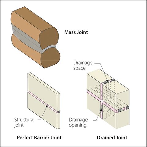
Joints may be classified in the same manner as enclosure elements—in other words, a joint may be designed using a storage, drained, or perfect barrier approach (Figure 3).
It is important to note enclosure elements and the joints between them can use different approaches. The joints between perfect barrier elements should almost always be designed as drained joints in the form of two-stage sealant joints or similar.
Rain control for joints and penetrations
Unlike some other systems, drainage or rainscreen approaches are not recommended for the overall design of an IMP wall. Insulated metal panels are inherently a perfect barrier (water obviously will not leak through steel) and should use a perfect-barrier rain-control approach. However, water can and will enter the enclosure through joints and penetrations.
IMP wall joints are made onsite (increasing susceptibility to workmanship errors) and comprise materials more likely to degrade (due to ultraviolet [UV] radiation and high and low temperatures). It is therefore critical these elements be drained.
The concept of a drained joint, or two-stage seal has been promoted for almost 50 years, (See two G.K. Garden articles—“Joints Between Prefabricated Components,” Building Note, No. 40, p. 5, Feb. 01, 1963; and CBD-97, “Look at Joint Performance” from the Division of Building Research, NRCC, Ottawa, 1968. See also American Architectural Manufacturers Association’s (AAMA’s) 1971 publication, The Rainscreen Principle and Pressure-equalized Design.) based on solid research, (See Sven Svendsen’s “The Principles of One-stage and Two-stage Seals” and T. Isaksen’s “Rain Leakage Tests on Through-joints”—both from the 1967 Weathertight Joints for Walls: Proceedings of the International CIB Symposium, Oslo, Norway. See also R.E. Platts and J.R. Sasaki’s “Rain Leakage Tests on Vertical Through Joints,” a Division of Building Research Internal Report (No. 23) from 1965.) and has been widely used with great success for almost as long in the precast concrete and curtainwall industries. In contrast, face-sealed polymer sealant joints (i.e. a single line of exposed sealant) have a poor record of performance and cannot be recommended for controlling rain entry.
Even exposed gaskets, often used to create the joint between insulated glazing (IG) units and the window frame, tend to shrink and crack over time. When these seals fail, as field experience shows is likely, significant water penetration occurs. (For more, see M. Lacasse and H. Miyauchi’s “Water Penetration of Cladding Components : An Overview of the Vulnerability of Sealed Joints to Water Penetration,” from the Proceedings of the 12th Canadian Conference on Building Science and Technology [CCBST], held in Montréal in May 2009.) For these reasons, a drained approach is recommended at joints for many systems, such as between the glass and frame of windows, between panels of precast concrete, and between IMPs and windows, doors, and other IMPs.
The interior seal in a two-stage joint acts to ensure both air control and water control continuity (Figure 4). The outer seal is a protective screen that ensures little water enters the joint, and the inner sealant is protected from UV radiation and temperature extremes. The inner seal can be installed from either the interior or the exterior and be formed of many different materials, although metal flashing and polymer-based sealants are the most common. Gaskets, unless mechanically compressed, do not usually provide sufficient tightness for the inner seal, but are often preferred for outer seals.
Generally, the inner seal should be held back about 25 mm (1 in.) behind the backer rod, gasket, or overlap of the outer seal to create a well-drained air gap. The gap can be deeper, if convenient, and often is in thick wall systems. Weep holes, with a minimum dimension of about 12 mm (½ in.), or continuous unsealed overlaps, must be provided to facilitate drainage. Weep holes are almost always installed at the base of vertical joints, and protected unsealed laps are used at horizontal joints on top of flashing. It is ideal, especially in enclosures highly exposed to wind-driven rain, to provide some protection for weep holes by adding exterior drip edges or extra layers of internal baffles to interrupt the direct kinetic energy of raindrops.
In addition to joints, window and door penetrations are critical to controlling rainwater. All enclosures should use a drained approach for window and door penetrations, regardless of the enclosure’s overall rain control strategy. Sub-sill flashings of various types are widely available to create a drained opening for windows and doors. For drained wall systems, the sub-sill flashing can drain into the drainage gap. For perfect barrier (e.g. IMP) and mass systems, the flashing must drain water to the exterior face of the assembly—that is, the water control layer of the rough opening must be made continuous with the water control layer of the wall.
Finally, fasteners must be considered. IMP systems must be fastened back to a primary structure to safely and effectively transfer the collected loads. This is usually achieved using fasteners and clip systems. These discrete connectors vary in shape and size amongst different IMP manufacturers. They may occur only twice along the length of a panel or every few yards. The design of these details, and the construction of the IMP enclosure, must account for these special penetrations or leaks of air and rainwater may occur. Through fasteners can either be hidden (and hence, protected) from direct rain impingement or exposed. In the latter’s case, they should be set in sealant or be provided with a pre-installed gasket and washer.
Air control in IMPs
Insulated metal panels meet all the requirements to be part of an air barrier. Sheet metal is clearly airtight, and hence is listed as an air barrier material in codes and standards such as American Society of Heating, Refrigerating, and Air-conditioning Engineers (ASHRAE) 90.1, Energy Standard for Buildings Except Low-rise Residential Buildings, without need for any additional testing.
Further, air leakage condensation cannot occur within the body of the IMP, even if one of the metal skins is breached, because all materials are completely air-impermeable and there are no empty voids to allow air flow. However, excessive air leakage at joints may be a problem if air leaks across the air gap and contacts a cold surface on the other side.
Therefore, as with rain control, air flow control in IMP systems depends primarily on the joints, penetrations, and transitions. Construction documents should detail how an uninterrupted, strong, and airtight transition from the inner sheet steel layer to the adjoining curtain wall, roof, canopy, foundation, etc., will be achieved while accommodating dimensional construction tolerances and in-service movement. Drained and vented joints should be used to allow incidental air leakage condensate and vapour to leave a joint, and will control condensation for small air leaks in most applications and climates. Of course, the vented outer joint cannot be part of ensuring air barrier continuity. Hence, the inner seal provides the continuity of the air barrier across joints.
For panel-to-panel transitions, high-quality, gun-grade sealants are preferred—compressed foam or butyl tapes often cannot accommodate the range of joint sizes demanded by dimensional tolerances on the jobsite, and polymer gaskets rarely remain pressed tightly to the metal skins. Protected interior seals made of quality polymeric sealant materials can usually provide service lives of 30 to well over 50 years. Mechanically clamped gaskets and membranes are usually practically difficult or too labour-intensive to install between panels, but are the preferred solution for joints between an IMP and another building component.
Sign up for our weekly newsletter
Construction Canada weekly newsletters give the latest AEC industry news for those who build, design, engineer, specify, renovate or operate in the built environment.
Related Products & Services

Read the Latest Issue