Designing with foam plastic insulating sheathing
Alternative solutions may be proposed by a qualified architect/engineer through a process commonly referred to as equivalency. As noted in the code commentary, “to do something different from the acceptable solutions described in Division B, a designer must show that their proposed solution will perform at least as well as the acceptable solution(s) it is replacing.” However, much of the language provided includes qualitative rather than quantitative metrics. Accordingly, alternative solutions may be unattainable in practice.
Material resilience
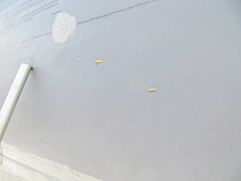
Polyiso is low density; this is an inherent property necessary to create the desired thermal resistance. However, low density also creates a material vulnerable to site damage during construction (Figure 5). Since FPIS in the non-redundant scenario provides all the building enclosure barriers, damage to FPIS means damage to the entire building enclosure assembly.
This is easily remedied where an issue is exposed; however, concealed deterioration is just as likely to occur. Where a cladding contactor lacks familiarity with FPIS systems, breaches may go unnoticed and become buried within the completed wall assembly. Requiring coordinated mockups with all parties participating in a joint discussion may limit this issue.
Common detail challenges
When designing an FPIS system, the transitions present the most challenging details. These details should not simply be delegated to the installing contractor, as often occurs. Failing to incorporate desired transition details may result in construction phase design changes and the associated change orders. Designers should pay close attention to roofing flashing transitions, at-grade transitions, and anything that may result in substrate and/or plane changes.
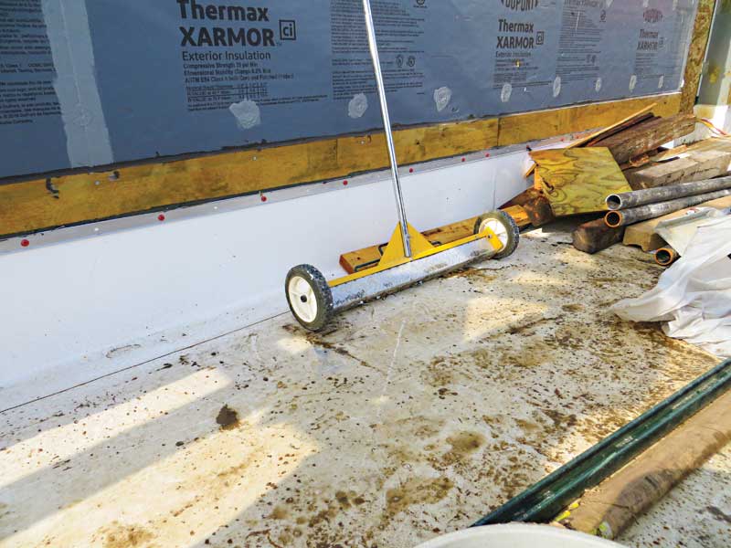
Depending on the type of roofing, direct attachment to FPIS may not be an option; hot-rubberized asphalt, which is frequently utilized at occupied terrace and plaza areas, cannot be applied directly to FPIS. Instead, the design may need to incorporate a separation layer (e.g. plywood or roofing cover board, see Figure 6). This separation layer will create an offset in the wall plane
requiring accommodation.
Consider metal counter-flashings. Even where compatibility is not an issue, the use of FPIS will likely impact the roof flashing termination; for starters, every termination will be surface-mounted, with functionality entirely reliant on a bead of sealant or liquid flashing product. Additionally, the backup wall may require metal strapping at the height of the termination bar to support appropriate fastening requirements.
Along the same lines, designers should be aware FPIS systems cannot typically be installed below-grade. For purposes of continuity, there should be a transition detail between the FPIS and the below-grade system, where applicable. XPS is frequently the insulation of choice below grade, with the damp proofing or waterproofing layer inboard of the XPS. In addition to the change in substrate, this transition may create a geometric offset that flashings will need to span. Broadly speaking, these are minor modifications. When incorporated into the design during the construction phase, however, their cost impact may be outsized.
Coordinated concepts
The importance of system co-ordination is universal, regardless of FPIS integration. That said, the design team for an FPIS assembly needs to consider there may be conflicting interests of the components. For example, structural engineers are taught to select the most efficient steel sections, including for structural connections. Where an exterior structural element ties to the backup wall system, it may be more valuable to enlarge the size of each connection to limit the overall number of connection points as each creates a breach in the air, weather, thermal, and vapour barrier system, and requires special detailing. It is at these penetrations where breaches are most likely to occur, therefore limiting the number of penetrations provides the best strategy for long-term success.
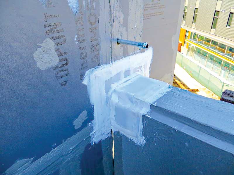
This becomes more complex where delegated design enters the picture. Cold form metal framing (CFMF) is often completed through the delegated design process. CFMF systems frequently incorporate movement provisions. Where the movement changes planes, the FPIS system must accommodate the same movement. For example, where a projected balcony interrupts a balloon framed CFMF wall, one segment of the CFMF may be loaded on the slab, while the adjacent portion extends down to grade (Figure 7). From the exterior there is little indication the FPIS system requires a specialized detail. While this could be addressed in shop drawings, it is uncommon to receive a shop drawing submittal from FPIS installers.
Sign up for our weekly newsletter
Construction Canada weekly newsletters give the latest AEC industry news for those who build, design, engineer, specify, renovate or operate in the built environment.
Related Products & Services

Read the Latest Issue