Designing the virtual air barrier
 The VAB concept has been applied to several buildings over the past 15 years. They include a heritage masonry office building over 75 years old in Toronto, a hospital less than four years old in Edmonton, a conference facility and roof of an eight-storey building in Ottawa, and several apartment buildings also in the capital.
A research and development project
The VAB’s proof of concept, as well as the architectural and engineering design criteria, was determined in a research and development project involving a six-storey heritage building. The building was clad with heavy masonry walls, metal-framed windows, and a convection hot-water-heating system or radiators at the windows.
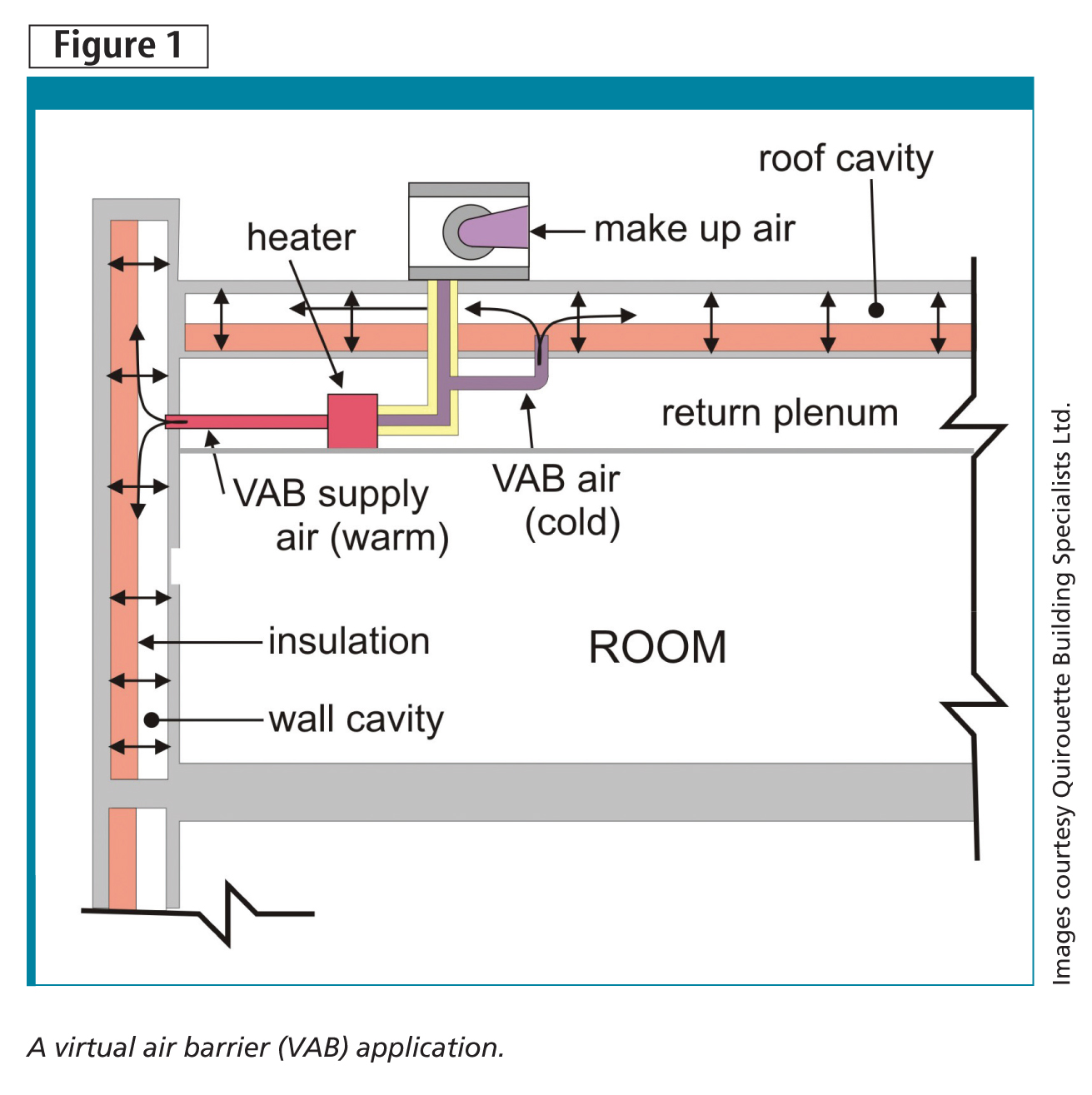
The test facility consisted of a single, long space facing east with multiple windows (Figure 2). In this project, the VAB was designed and constructed for the building’s exterior walls and steel-framed windows. The indoor rooms were equipped to maintain a constant temperature and to produce high-humidity conditions. Part of the exterior wall and windows of the test area was isolated to provide a ‘control-room’ cavity separate from the VAB exterior wall.
This control wall was isolated from the VAB wall by a compartment seal (i.e. interruption of the wall cavity), which allowed part of the existing exterior wall to be exposed to the same indoor conditions while retaining its original exposure and performance attributes. The control and VAB walls were both equipped with visual and electronic monitoring equipment for observation of condensation control performance over a heating season.
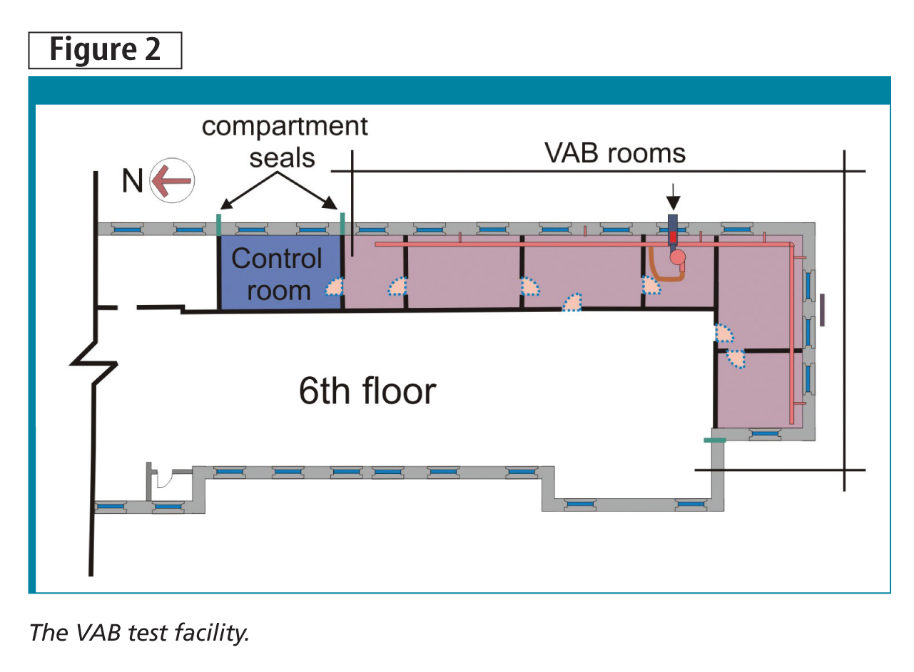
The building’s masonry wall was constructed of 100 and 200-mm (4 and 8-in.) granite stone, with two layers of 100-mm terra cotta bricks mortared together with the stones (Figure 3). The stones were anchored to the terra cotta masonry with metal brackets. A 50-mm (2-in.) cavity separated the stone and brick cladding assembly above from an interior layer of terra cotta brick with a plaster finish.
There were many holes and openings in the plaster finish. Pipes were found within the wall cavity servicing a hot-water heater just below the windows, which comprised two single-pane glazed panels in steel frames with a 100-mm (4-in.) space between.
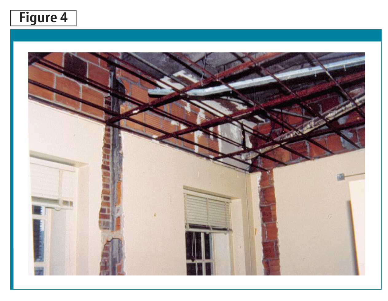
The test exterior wall and windows were then sealed on both the outdoor and indoor sides—the cladding face and indoor plaster finish, respectively. The exterior wall’s continuous cavity was divided into two parts: the ‘control room wall cavity’ and the ‘VAB zone cavity.’ The cladding face or exterior stone work was repointed. Where required, the interior exposed terra cotta blocks were sealed with gypsum board and taped joints (Figure 4). No attempt was made to supper-seal the VAB zone or the control cavity. In other words, pencil-sized holes and fine cracks were ignored, but pipe openings were sealed with gypsum board tape and joint compound.
The test facility’s room side was furnished with a humidifier capable of delivering up to 4.54 kg (10 lb) of water vapour per hour. The room temperature was set and maintained at 20 C (68 F).
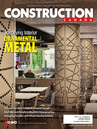
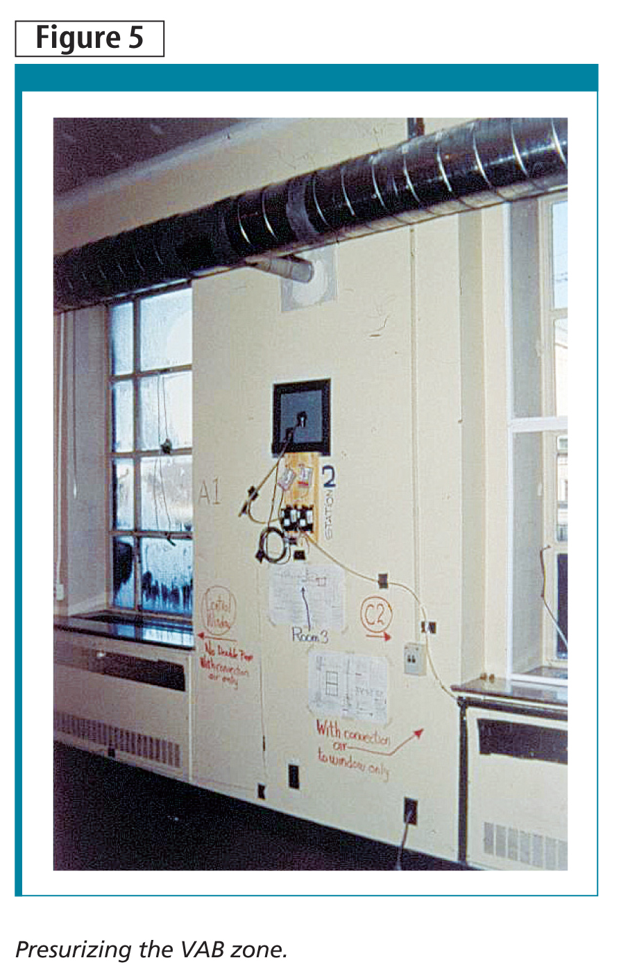
To pressurize the VAB zone, an insulated duct was installed through one of the windows. The outdoor side was protected against snow penetration by a grilled opening. On the indoor side, the insulated duct was equipped with an inline heater to preheat the outdoor supply air to a maximum of 10 C (50 F). The duct was further equipped with an inline fan capable of delivering up to 240 L/second (500 cfm). The system supplied and pressurized the VAB zone through duct branches installed through the indoor plaster finishes (Figure 5). The pressurization air was controlled with a variable speed controller and a temperature thermostat. To ensure against over-pressurization, the supply fan was selected with a maximum head pressure of 125 Pa (0.5. in.H20). Most exterior walls or roofs are designed to support five to eight times as much pressure difference from wind alone. There is no need for additional pressure-relief equipment.
To validate the performance of the VAB concept and its application, observations were visually recorded once a week and continuously with electronic monitoring equipment. Visual observations were recorded by noting conditions on the outside of the building near the exterior wall, and on the indoor side of both rooms. The control cavity and VAB zone were equipped with metal door inspection hatches. The hatches allowed a view of the back surface of the wall control cavity and the VAB cladding masonry. Each masonry wall had a 100-mm diameter hole drilled in the layers of terra cotta brick, exposing the back of the granite cladding stone.
Electronic monitoring and observations consisted of measuring the temperature, relative humidity (RH), and air pressure difference at various locations of a wall. These locations included monitoring sensors on the outdoor side, in the cavities of the VAB zone and control wall cavity, and on the indoor side of the rooms. Data was recorded every five minutes and downloaded to data loggers for retrieval at the end of each week. Monitoring continued uninterrupted for nearly six months. The records were then plotted and analyzed.
Sign up for our weekly newsletter
Construction Canada weekly newsletters give the latest AEC industry news for those who build, design, engineer, specify, renovate or operate in the built environment.
Products & Services


Read the Latest Issue