Designing barrier-free showers
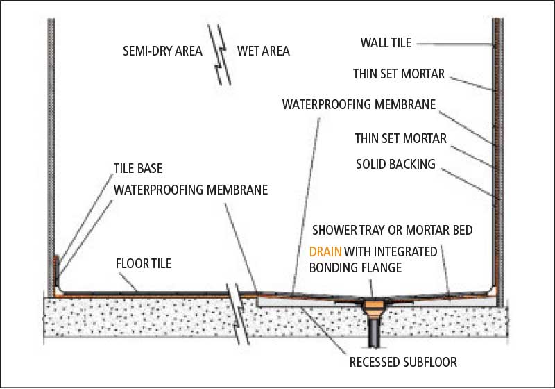
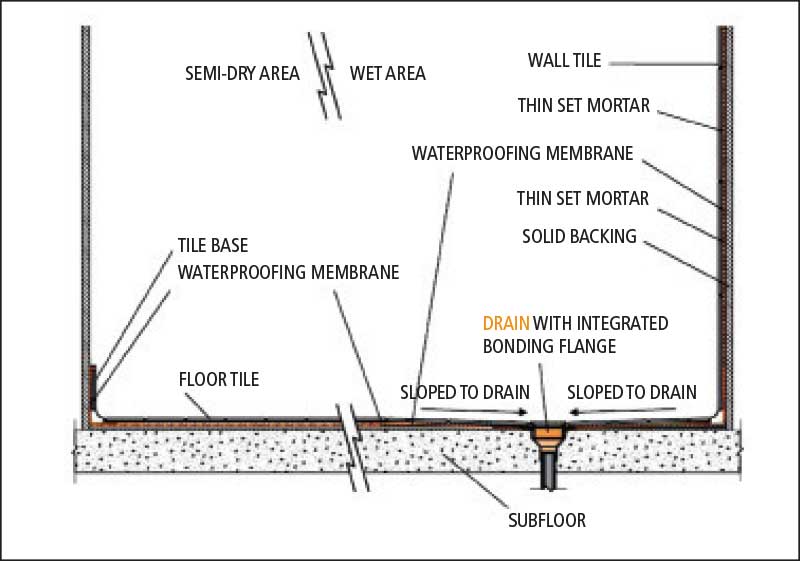
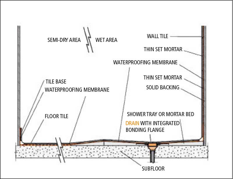
Slope can be started from almost zero and, again, depending on the size of the shower room, heights can be maintained relatively low. For instance, a shower with a 1220-mm (48-in.) radius will have a construction height of only 24 mm (1 in.). These membranes are typically continued up the wall onto solid backing to ensure the assemblies are waterproof. In other cases, a high-density expanded polystyrene (EPS) board with bondable/waterproof facers can be substituted if nothing has been attached to the studs. The advantages of these boards are their light weight, R-value, vapour resistance, and the fact they can be cut with a utility knife onsite.
Another new entry into barrier-free bathrooms that expands the design opportunities is the introduction of linear drains. Several manufacturers have launched products that allow drains to be placed in different strategic locations. Most of them work with an ANSI A118.10 membrane and, like the integrated bonding flange drains, the linear drains allow for low construction height assemblies as they can be installed directly onto the substrate. Additionally, employing a linear drain enables the design of floors that have only one or two slopes, which allows for large-format tile or even stone slabs to be installed in the shower area.
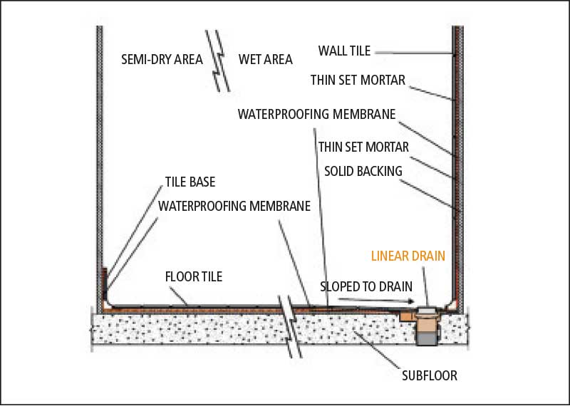

Standard drains that are 100 to 150 (4 to 6 in.) x 100 to 150 mm only allow use of small-format tile because the floor either has to be designed in a cone configuration or made into four planes to direct water to the drain. In most cases, tiles no larger than 305 x 305 mm (12 x 12 in.) can be used to evacuate water. Linear drains, on the other hand, can be placed:
- adjacent to the wall where the showerhead is located, which would allow for a single slope;
- in the middle of the shower floor that would have two slopes converging to the drain; or
- in the threshold in front of the shower area, which also would allow for a single-slope floor.
Avoiding slips and falls
The number-one culprit of injury in both residential and commercial applications is slip-and-fall incidents. Until recently, the main test method used by the tile industry to determine slip resistance was ASTM C028, Standard Test Method for Determining the Static Co-efficient of Friction of Ceramic Tile and Other Like Surfaces by the Horizontal Dynamometer Pull-meter Method, which is also known as the static co-efficient of friction (SCOF) test.
However, this test method was somewhat controversial as test results were not always consistent; there were also concerns for the testing of wet conditions regarding a condition called ‘stiction’—a surface tension phenomenon similar to how two plates of glass with water in between stick together. This would give artificially higher ratings in comparison to the actual traction of the surface in question.
This year, with the revision of the TTMAC Tile Installation Manual, it was decided to withdraw use of ASTM C1028 for slip resistance and acknowledge a new test that has been ratified and referenced in ANSI A137.1-2011, American National Standards Specifications for Ceramic Tile. This new test method—which has been designated as the dynamic co-efficient of friction (DCOF) Acutest—employs the BOT 3000, a type of testing apparatus that measures parameters in the field of tribology, such as frictional forces, co-efficient of friction, and effects of lubrication.
In the past, using the ASTM C1028 test method, the recommended SCOF was 0.5 wet as recognized by the revised TTMAC Tile Installation Manual. Now, employing the new BOT 3000 testing apparatus, the designated threshold value of 0.42 or greater has been designated for interior spaces expected to be walked on when wet. To determine whether a specific tile or stone will meet this criterion, TTMAC or another third party can conduct this test at a nominal charge.
Sign up for our weekly newsletter
Construction Canada weekly newsletters give the latest AEC industry news for those who build, design, engineer, specify, renovate or operate in the built environment.
Products & Services


Read the Latest Issue