Designing and building with tensile architecture
By Michele Roth
Tensile architectural systems provide projects with a unique look, and give design professionals the ability to experiment with form. Today, the applications and capabilities of tensile structures have evolved into permanent structures such as retail centres, office buildings, institutional facilities, museums, and stadiums.
What has typically been thought of as a building material reserved for large-scale projects, tensile systems are being more often specified for small- and medium-sized projects, including travel and hospitality attractions.
However, with the advent of more tensile structures come potential pitfalls architects need to understand. This is why it is critical for architects and engineers to establish effective, knowledgeable project teams.
Beautiful, strong, flexible, and complicated
In conventional post-and-beam construction, weight and rigidity is a requirement, as these types of materials are placed in compression and bend to create structural integrity. Vertically aligned posts work in compression with horizontally aligned beams in bending to create structure. However, with tensile construction, lightweight, flexible, and elastic materials are preferred—structural form and integrity is created by adding tension.
Owing to the membrane’s light weight and strength, it spans long distances far more efficiently and economically than conventional roofing structures and cladding systems such as metal, tiled roofs, or flat glass. In contrast, conventional roofing products are generally limited to smaller panel sizes around 6 m (20 ft) or less. The more panels required, the more joints are required, creating a greater opportunity for failure. The nominal maximum span for tensioned membrane from the factory is up to 12 m (40 ft) in width and 90 m (300 ft) in length. Widths up to 12 m are achieved by fusing membrane panels with a heat weld. This seam becomes weather-tight and as strong as the membrane itself.
While there are numerous membranes with different compositions available, today’s most widely specified membranes are polytetrafluoroethylene (PTFE) fibreglass. PTFE is a Teflon coating applied to woven fibreglass to form a durable fabric membrane. It can be installed in any climate, and has a life expectancy in some instances exceeding 30 years. It is chemically inert, making it completely immune to ultraviolet (UV) radiation.
Broadly speaking, any dust, dirt, or ash that settles on the PTFE membrane can be easily washed off with water. Normally rainfall is sufficient to accomplish this, but the use of mechanical spraying to return the fabric to its original brilliant white appearance can be required. PTFE is also ideal for applications requiring superior durability and fire resistance.
PTFE fibreglass is comprised of multiple layers. The woven fibreglass substrate gives the PTFE material its mechanical strength. The filaments, known as beta glass, are the smallest diameter available and provide the membrane with maximum flexibility. The fibres are drawn from hot melted glass through platinum dies into continuous filaments, and are then twisted and plied into yarn bundles. The yarns are woven into large expanses of structural fabric and coated with PTFE to complete the process. PTFE fibreglass yarns maintain ultimate tensile strength of 3.5 million kPa (500,000 psi), and a modulus of elasticity of 10.5 x 10⁶ compared to steel, which offers 200 million kPa (29 x 106 psi). Under normal conditions, the fabric behaves elastically and does not undergo significant stress relaxation or creep.
PTFE fibreglass has a long list of performance and esthetic benefits, including durability, historical life span performance, strength, and self-cleaning characteristics. Additionally, PTFE fibreglass has excellent fire performance, passing:
- National Fire Protection Association (NFPA) 701, Standard Methods of Fire Tests for Flame Propagation of Textiles and Films;
- ASTM E84, Standard Test Method for Surface Burning Characteristics of Building Materials;
- ASTM E108, Standard Test Methods for Fire Tests of Roof Coverings;
- ASTM E136, Standard Test Method for Behaviour of Materials in a Vertical Tube Furnace at 750 C.
These performance characteristics make PTFE fibreglass a well-suited material for permanent enclosure and shelter applications. Further, the newest generation of PTFE fibreglass membranes are offered with coloured and metallic finishes, simulating traditional metal cladding finishes.
Case study: Hornblower Niagara Ticketing Plaza
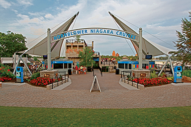
One example of a small project employing a PTFE membrane is the Hornblower Niagara Ticketing Plaza in Niagara Falls, Ont. When Hornblower Cruises and Events took over the famous Maid of the Mist boat tours, they recognized the need for something special at the ticketing plaza.
“The most common feedback we got from customer surveys was tourists could not easily locate the boat tour,” said Hornblower Companies vice-president, Brian Stewart. “What we needed was an attention-grabbing gateway to greet the two million people who ride the boat tours each year, while at the same time honouring the area and its nautical history.”
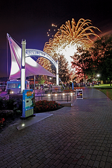
Hornblower turned to long-time architect Heller Manus Architects out of San Francisco, who worked with Ontario-based firm Chapman Murray Associates Architects. Their combined solution was two iconic sail-shaped membrane structures to serve as a recognizable gateway to tourists.
“While Hornblower had conceptually considered using tensile architecture before on other projects, this was the first implementation,” added Stewart. “We did look at more standard designs, but we decided it should really be a beacon for the destination.”
With this goal in mind, the project team created a design developed to present a powerful image to attract visitors and create a smooth pedestrian flow for ticketing and entry.
“The design reinvigorates a long-standing world-class destination that dramatically improves the visitor experience and the operation for Hornblower,” said Heller Manus’ Clark Manus, FAIA.
Seen and unforeseen challenges
With the design in hand, the project team began bringing the vision to reality. However, every construction project has its challenges; this one dealt with several, both above and below ground.
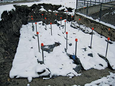
First, the team faced serious time constraints. Since Hornblower wanted to begin the 2014 season with a new ticketing plaza, all the work had to begin at the end of 2013. This timing led to another challenge—weather. The cold climate would not be easy for the crew that would have to put in long days outdoors.
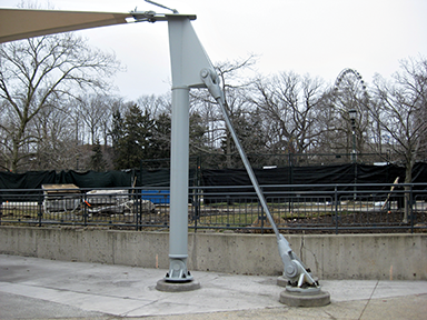
Another challenge was to determine how these structures would be stabilized underground. While these were sail-shaped structures, they would not be functioning like typical sails. However, they were being placed in an area with strong wind—creating strong pressures that needed to be counteracted in order to ensure the structures were securely anchored.
Normally, to stabilize this type of structure, teams would create a tie-down to the ground by excavating a large hole in the earth, pouring in concrete and reinforcing, then attaching the steel structure and fabric on top. This was the plan for this project, until engineers reviewed the architectural drawings.
Al Antonio, the structural engineer, was familiar with the Niagara Falls area and knew the bedrock would be quite shallow. Therefore, simply drilling down and pouring concrete foundations would be impossible.
The team brought in a geo-technical expert and determined the bedrock would be 0.6 to 1.2 m (2 to 4 ft)
from the present grade. A decision had to be made to go below the bedrock to anchor these structures. Once that decision was made, engineers needed to ensure these concrete foundations would fit within the Niagara Parks Commission property. Due to the site’s historical nature, the team had to ensure it did not interfere with plant life and trees on the land.
After digging had commenced, the team discovered two historical electrical conduits underground. These conduits, which had been in the ground for more than a century, were approximately 0.6 to 1.2 m tall and ran for several hundred metres.
While the team’s first reaction was to simply reroute the conduits, the Niagara Parks Commission wanted them to be preserved for future use. Avoiding these conduits proved particularly difficult as they were situated directly under where two foundations were planned to go.
Finding solutions
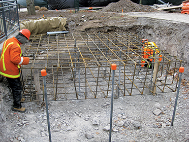
In order to make this engineering feat possible, the design team provided detailed directions for contractors, including enlarged details of the locations where the anchor bolts needed to be.
“This project required extreme exactness,” said Antonio. “It was quite critical they were exact because the anchor system is such that there’s a large base plate under the columns. If even the angle of the base plate, with regards to a compass point direction, was off by two or four degrees with the anchor bolt, the base plate that has been welded to a column or a structural member above it would not fit.”
To preserve the electrical conduits, engineers updated the steel supporting structures to include a tripod and different columns. Underground, the team found by bridging over the conduits they could preserve them, but also ensure the structures were secured. The majority of the difficulty and the solution took place underground.
Despite the challenges the design-build team faced, the project was completed on time and the structure’s esthetic was preserved.
Finding the right team
Tensile architecture permits design flexibility and can be used for projects of various sizes. However, when building with tensile architecture, it is imperative to have a qualified and experienced team. One major team player in any tensile architecture project is the specialty contractor for tensile membrane structures. This contractor should do much more than just supply the materials.
The value of a tensile membrane contractor is directly related to its expertise and experience. The contractor should have a team of specialty engineers, consultants, and designers highly skilled and experienced, working with the latest custom tensile architectural materials and steel cable structure systems. Through engineering analysis and peer review, the contractor should deliver reaction loads, connection details, member sizing, interface details, and construction methodologies. A contractor with these offerings can provide an efficient high-quality structure.
During the fabrication stage, it is important the contractor’s manufacturing plant is International Organization for Standardization (ISO)-certified and is capable of fabricating a wide array of fabric membranes, such as PTFE, polyvinyl chloride (PVC), and ethylene tetrafluoroethylene (ETFE) film. This in-house capability allows the contractor to meet fast-track schedules and control production quality.
Once a project has been approved through design development, and the manufacturing and testing phases are underway, contractors, project managers, and engineers should meet to review the construction methodology and co-ordinate erection procedures and scheduling. Additionally, one must consider if the contractor has enough experienced site superintendents to allow them to properly supervise all their projects.
The final thing to look for in a tensile architecture contractor is their commitment to customer service. With tensile architecture, it is imperative the customer service does not end simply because a project is completed. The contractor should offer clients a wealth of post-project resources and assistance. These services can range from simple cleanings to comprehensive structural reviews and modifications.
Conclusion
There are many advantages and functional benefits of PTFE structures. Particularly, these membrane structures provide various designs of distinctive forms that are possible because of the membrane’s flexible characteristics. With several different membranes in the market, such as PTFE fibreglass, the durability and longevity of tensile membrane structures have been proven and built in climates ranging from the frigid artic to the scorching desert heat.
Most PTFE structures have high sun reflectivity and low absorption of sunlight, resulting in less energy used within a building and ultimately reducing electrical energy costs. In daylight, fabric membrane translucency offers soft diffused naturally lit spaces reducing the interior lighting costs while at night, artificial lighting creates an ambient exterior luminescence.
Further, the lightweight nature of membrane is a cost-effective solution requiring less structural steel to support the roof compared to conventional building materials, enabling long spans of column-free space. PTFE membrane systems are somewhat unique in that they require minimal maintenance when compared to an equivalent-sized conventional building. Finally, depending on the type of membrane and overall project design, PTFE systems can meet the various associated building code requirements.
 Michele Roth is business development manager at Birdair, a specialty design build contractor of custom tensile structures throughout the world. After seven years with the company, her responsibilities include new business development and sales for tensile membrane projects in the Northeast region of the United States while fostering and maintaining good relationships with architects, engineers, owners, and developers. Roth earned a bachelor’s degree in business administration from the State University of New York (SUNY). She can be contacted via e-mail at mroth@birdair.com.
Sign up for our weekly newsletter
Construction Canada weekly newsletters give the latest AEC industry news for those who build, design, engineer, specify, renovate or operate in the built environment.
Products & Services


Read the Latest Issue