Design integrating copper cladding
Images courtesy CDA and CCBDA

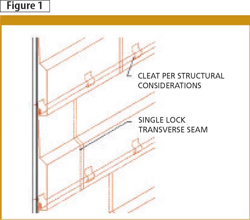
Profiled panels
Illustrated in Figure 1, profiled copper panels come in various shapes and sizes. The shapes can be formed onsite with a brake or powered forming equipment. They can also be pre-manufactured and specified with embossed patterns or other designs.
The minimum recommended weight for copper used on profiled panels is 454 g (16 oz), but some panel profiles require heavier material. Support blocking behind the panels could be necessary depending on panel thickness, dimensions, and straight or curved wall configuration.
Horizontal flat-lock assemblies
The horizontal flat-lock wall panel assembly (Figure 2) is basically identical to flat-seam roofing applied on a vertical surface. However, neither solder nor sealant is required in the joints, since the vertical surface provides positive drainage.
The panels are typically 457 x 610 mm (18 x 24 in.), with 19-mm (3/4-in.) folds on all four sides—two sides over and two under. All corners are trimmed at a 45-degree angle and single-lock seams are typically hammered flat. The minimum recommended gauge is 454-g (16-oz) copper and each cleat is fastened with two stainless steel screws.
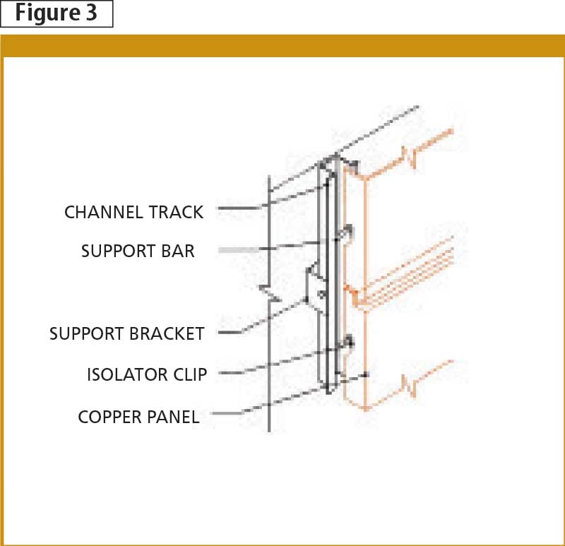
Copper screen panels
Copper screen panels are part of a manufacturer’s engineered assembly. The details shown in Figure 3 illustrate the main concepts in the design of these panels. This system uses metal support brackets and channel tracks to carry copper panels, and support brackets can be attached to virtually any kind of building structure. The copper screen panels act as a lightweight finish screen; the system shown in Figure 3 is designed to be a water-shedding rainscreen. Alternatively, the panels can be perforated or have shaped openings acting as sun- or decorative screens, and the backup wall system should always be designed to be watertight.
Isolator clips are used between the metal support system and the copper panels to separate dissimilar metals. The minimum gauge of the copper panels depends on the size of the panels and the design of the specific system used. Manufacturer’s recommendations should be followed.
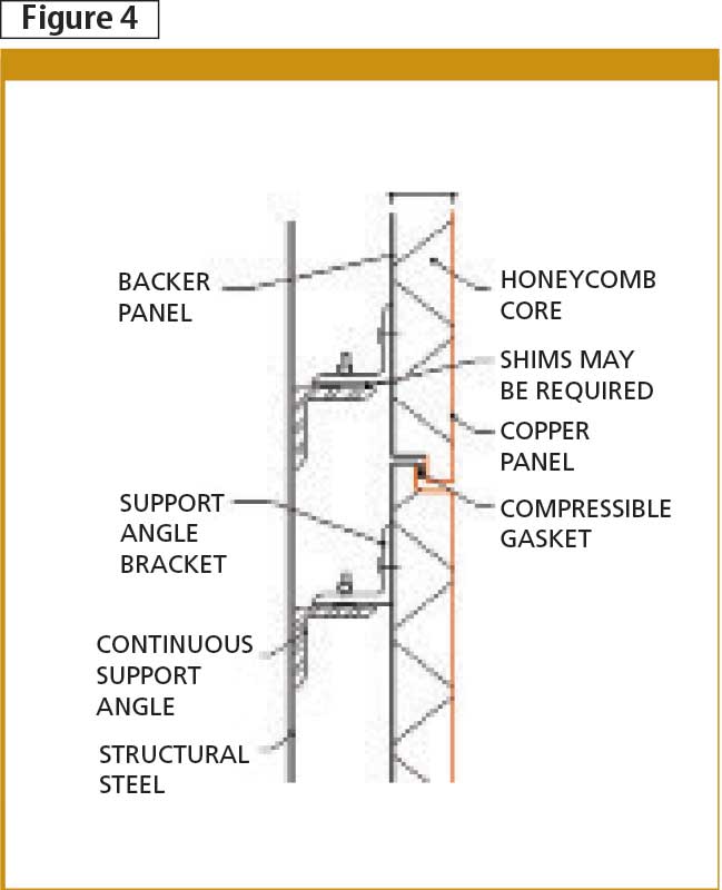
Copper-clad honeycomb assemblies
Copper-clad honeycomb panels are engineered and fabricated by a variety of manufacturers (Figure 4). They are lightweight, strong, and offer a flat copper panel appearance. Total panel thickness is variable to suit project requirements.
The honeycomb material varies by manufacturer, and whether it is an interior or exterior application. Copper is bonded to the front side of the honeycomb and a backer panel is bonded to the back. The backer panel is usually a material compatible with the structural system. It is required to ensure the assembly’s rigidly, thereby minimizing warping.
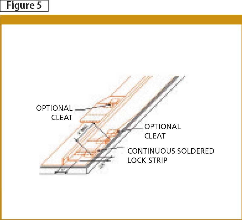
Standing-seam wall cladding
Standing-seam wall cladding is composed of preformed or field-formed panels, usually about 457 to 610 mm (18 to 24 in.) wide when finished (Figure 5). Typically, a 454-g (16-oz) copper sheet is used for examples of standing seam cladding. A 567-g (20-oz) sheet can be used when pans are wider than normal, or where increased rigidity is required. These panels may run vertically or horizontally to the desired wall and are joined to adjacent panels with double-locked standing seams. Fixed copper cleats, spaced 305-mm (12-in.) apart and locked into these seams, secure the cladding.
When preformed panels are used, they are joined at their upper and lower ends by transverse seams. These seams should be staggered for adjacent panels to avoid excessive thickness of copper at the standing seam.
Finally, field-forming involves the use of copper in flat sheets or rolls that are formed into panels. Long rafter-length segments can be made, eliminating the need for transverse seams, but corner and rounding details must allow for copper expansion and contraction characteristics.
Conclusion
With new copper cladding techniques being integrated into building design, architects, specifiers, and contractors now have more construction options. The industry has seen a sharp increase in the number of copper wall cladding installations throughout North America, pointing to a new trend in how copper and its alloys are being applied. The material’s esthetic appeal, longevity, and malleability lend its use to both residential and commercial projects.
Stephen Knapp, B. Tech., Arch. Sci., M. Arch., is the executive director of the Canadian Copper and Brass Development Association (CCBDA). He is responsible for guiding the market development and promotional efforts for applications of copper and copper alloys, including tube and plumbing, electrical, renewable energy systems, and architectural applications such as roofing and cladding. Knapp can be reached at sawknapp@coppercanada.ca.
Sign up for our weekly newsletter
Construction Canada weekly newsletters give the latest AEC industry news for those who build, design, engineer, specify, renovate or operate in the built environment.
Products & Services


Read the Latest Issue