Characteristics of high-performance air barriers
by sadia_badhon | September 10, 2020 12:11 pm
By Peter Barrett
 [1]
[1]An airtight building enclosure is an important part of a modern building. Airtightness is achieved with an effective air barrier system that is carefully designed and detailed, then built and commissioned in the field. An effective air barrier consists of a continuous system of materials, components, and accessories, and not an individual product.
Achieving airtightness on the open area is easy. However, the majority of air leaks occur at transitions and interfaces between building elements. Successfully managing the inevitable joints, laps, penetrations, and fastener holes differentiates a good, high-performance air barrier system from an ineffective one.
Air barrier function
Every functional enclosure design needs to identify which wall layers are responsible for water, air, thermal, and vapour (diffusion) controls. Each control function has different requirements. Hence, one must know what function each layer is serving to judge whether it will live up to performance expectations. A useful way to think about the different layers is widely known as the ‘perfect wall[2]’ concept. The perfect wall is a blueprint requiring four principal control layers, in the following order
of importance:
- rain;
- air;
- vapour; and
- thermal.
The system providing air control typically includes a number of materials working together. The overall system also must meet a few criteria.
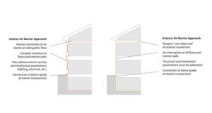 [3]
[3]Images courtesy RDH Building Science
System continuity
A complete air barrier system[4] is a combination of several assemblies and components connected by multiple accessories that are designed to provide a continuous barrier to the movement of air through an environmental separator.
When it comes down to it, high-performance air barrier systems[5] must have the following characteristics:
- continuous (most important);
- strong enough to withstand forces during and after construction;
- stiff to help absorb and transfer wind loads evenly;
- durable to last the expected lifetime of the building; and
- impermeable to airflow (least important factor).
The reason for this order is that an air-impermeable component will be ineffective without continuity. An air barrier system must meet several requirements, but continuity is the most important and challenging characteristic to achieve in modern steel, wood, or concrete buildings.
The interior air barrier approach is common for residential buildings. The detailing for continuity is considerably more difficult because of penetrations and transitions. The exterior approach involves fewer penetration details and is easier to inspect for discontinuity. A fully supported (rigid) air barrier installed on the outside of the structure is the most likely approach to meet the performance criteria. For commercial buildings, sometimes the only solution is an exterior air barrier solution (Figure 1).
Airflow in the ventilation cavity or within the stud space causes cooling or ‘wind washing’ (i.e. air movement driven by wind pressures causing energy loss and condensation) of air-permeable insulations. This is why air barriers must be thought of as a system, and not a product. Even though air movement into and out of the building is controlled, unrestricted air movement through the stud space can increase energy consumption and moisture risk, reduce R-value of insulation, and cause discomfort to occupants.
 [6]
[6]Requirements for airtightness
Air barrier requirements have brought significant changes to detailing. The focus is on the performance of the whole building, and not that of individual materials. The different requirements for air barrier components and systems are:
- ASTM E2178, Standard Test Method for Air Permeance of Building Materials, and Underwriters Laboratories of Canada (CAN/ULC) 741, Standard for Air Barrier Materials – Specification; and
- ASTM E2357, Standard Test Method for Determining Air Leakage Rate of Air Barrier Assemblies, and CAN/ULC 742, Standard for Air Barrier Assemblies – Specification, for components.
There are many standards worldwide detailing whole-building tests, including:
- The International Organization for Standardization (ISO) 9972:2006, Thermal performance of buildings – Determination of air permeability of buildings – Fan pressurization method;
- ASTM E779, Standard Test Method for Determining Air Leakage Rate by Fan Pressurization; and
- ASTM E1827, Standard Test Methods for Determining Airtightness of Buildings Using an Orifice Blower Door.
For more than 20 years, the National Research Council Canada (NRC) has recommended limiting air leakage[7] across the enclosure of commercial buildings to a maximum of 2 L/s/m2 at a pressure difference of 75 Pa. This is the minimum requirement. Buildings are often designed and built to tighter air leakage standards.
By using whole-building airtightness tests and by setting performance targets, architects and contractors can quantitatively verify if the methods used were successful. They can also be employed diagnostically on new construction, remedial projects, and major energy-efficiency retrofits.
The National Energy Code for Buildings (NECB), which applies to Part 3 or commercial and institutional buildings, and the National Building Code’s (NBC’s) Section 9.36, which applies to Part 9 or small buildings and houses, are key components of the model code system defining the minimum energy-efficiency requirements for new buildings. NECB and NBC 2020[8] are now in the final stages of their 2015-2020 development cycle. The new version of NBC is expected to be published in December 2020.
Building testing is not mandatory for commercial buildings, but is a performance-based option that many designers require. The only Canadian jurisdiction mandating the blower door test is the City of Vancouver, as part of its Green Building Strategy for one- and two-family homes.
A national model for a four-tiered code is in development for each model code (NECB and NBC), similar to the B.C. Energy Step Code that was launched in 2017. A tiered code is an incremental approach to achieving more energy-efficient buildings. It is a series of steps starting with a base building code.
NBC is proposing a concept of ‘tiered performance’ for structures described under Part 9 buildings. These structures are not more than three stories high, and less than 600 m2 in area. Buildings falling under Part 3—larger residential, commercial, and institutional structures—will follow an advanced energy model that will compare the proposed facility’s performance to a ‘reference structure.’
Detailing connections and transitions
Final airtightness of a building depends on the airtightness of many critical details in the building enclosure design, including windows and structural (e.g. balconies) and mechanical penetrations. Each of these details can be improved through careful attention to continuity during the design phase and quality control throughout construction.
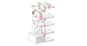
The ‘perfect’ approach means details such as transitions between wall and roof assemblies need attention and someone must be clearly responsible for each. In Figure 2, red circles represent critical and challenging detail areas. The blue dotted line represents the plane many architects draw
in detail.
Each red circle requires a scaled drawing. If the drawing lacks details, then the contractor who may not have the experience will decide the best course of action, potentially sacrificing critical continuity. Every detail needs to be addressed by the designer.
The transitions of components cause many challenges for building enclosure installers. At the same time, inexperienced designers may not identify these difficulties and fail to detail complex areas in full. Designers should not assume all installers will be able to identify breaches and correct them to ensure a continuous barrier has been created during installation.
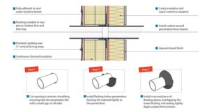 [9]
[9]Window penetrations are the most common detail because nearly every wall has one. The window must be tied into the air barrier system to ensure airtightness. It is best to follow the line of the air barrier and note the window connection to the air barrier plane. Critical points with window detailing are the corners. Prefabricated corners can be easier to install and help ensure air- and water-tightness. It is also critical, even in a vapour permeable system, to use vapour-impermeable materials at the window sill where standing water is a risk.
The wall-to-roof transition can be a difficult air barrier detail for both contractors and designers. Where walls intersect the underside of the metal roof deck at overhangs or soffits, light-gauge metal plates can be sealed and fastened to the topside and underside of the deck and wall, and roof air barriers can connect directly to these plates. The top and bottom metal roof deck flutes need to be sealed to prevent airflow between the plates.
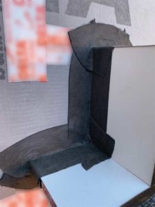
Lastly, there are other structural penetrations such as balconies, exposed slab edges, and intentional holes left to accommodate services like plumbing. These are major contributors to poor airtightness. Just like windows, each must be detailed to maintain continuity (Figure 3).
The pencil test
One of the best tools to begin the building envelope commissioning process during design is to perform a “pencil test” on a building cross-section or floor plans.
Take a pencil and, starting in the lower right-hand corner of the drawing, trace the line of each of the barriers moving upward along the walls, horizontally across the roof, back down to the footing, and horizontally across the lowest floor and back to the point of beginning. The areas where the pencil encounters anything other than a smooth, continuous plane is circled to identify potential areas of barrier interruptions. These include wall penetrations, fenestration openings, offsets,
or changes in materials.
Each circled area represents an architectural detail that is required to communicate how the barriers connect and remain continuous. Those details must be thought through and shown on the final construction drawings to ensure the barrier can indeed be constructed as continuous. It is no longer enough or appropriate to simply mention ‘continuous’ in a note identifying the barrier—it must be accompanied by an architectural detail.
Quality control during construction
The importance of the air barrier is more widely understood, but disconnect between design and installation is not always given the attention it deserves by project teams. Insufficient drawing details at transitions and intersections can result in breaks in the air barrier and increased air leakage across the building enclosure plane at the point of installation.
In some cases, the construction manager and subcontractors do not have a fundamental understanding of the air barrier. As a result, breaches in the air barrier due to difficult transitions are unidentified during construction, and subsequently repaired. However, instilling quality control methods during design and construction minimizes the risk of damage associated with a leaky air barrier.
First, consider full-scale, onsite mockups to illustrate and review details and conditions found in the overall project. This offers the installing contractor an opportunity to review the assembly, sequencing, and constructability of the various components. All participants can see and agree upon the critical details upfront and prior to large-scale assembly.
The lab test for a mockup is CAN/ULC 742 or ASTM E2357, Standard Test Method for Determining Air Leakage Rate of Air Barrier Assemblies (both acceptable under NBC, but the CAN/ULC test also involves temperature differentials, so it is preferred by Canadian designers). However, it should be determined before the mockup stage if those standards are being met.
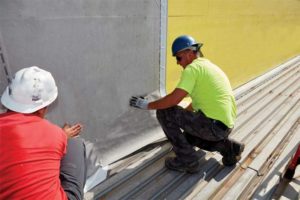
Second, pre-installation meetings are a simple way to ensure co-ordination of all onsite workers. It is important to include not only the installing contractors for the air barrier, but also the tradespersons responsible for overlying components. Insist on a meeting where the wall air barrier, roofing, and waterproofing contractors discuss edge conditions and the overlapping of materials, potential time delays between the installation, and other co-ordination issues to ensure a continuous air barrier.
 [10]
[10]Photo courtesy Dörken Systems Inc.
When the products are ready to be installed, specify the contractor examines the substrate assembly and adjacent materials, including the surface preparation for the air barrier and the treatment of joints between the products. Specify flashing and transition materials needed to bridge the gap between window assemblies and roofing or walls. Also include specification for repair of damaged air barriers and substrate conditions. It is advisable to always stress continuity and the co-ordination with other trades.
Field inspection
As part of the air barrier installation, the contractor or third-party inspector should conduct an air barrier quality control program that includes:
- inspecting all materials to ensure conformity to contract requirements and confirm all materials are not damaged or stored improperly;
- checking all surface preparation prior to installation of the air barrier;
- assessing in-progress work to ensure it is being done in accordance with established procedures, third-party standards, or instructions from manufacturers and the project’s architect; and
- obtaining all air barrier materials and accessories from a single manufacturer and providing other system components only as approved by the manufacturer of the primary materials.
Additionally, the architect on record or third-party inspector should conduct field evaluations during the air barrier installation and afterward. These inspections should include a visual check to confirm it is continuous and an adequate bond is achieved to each substrate specified for the project.
Case study
Anyone who knows luxury vehicles also understands state-of-the-art sales and service facilities are part of the prestige that comes with them. Budds’,
a Canadian chain of luxury car dealerships, has taken this tradition to heart for its Jaguar and Land Rover dealership by building a new, fully equipped, premium building that better reflects the quality and luxury for which its imported products are known.
Located in Oakville, Ont., the new Budds’ Jaguar and Land Rover dealership is a 7432-m2 (80,000-sf) building completed in 2018. It was designed by R.H. Carter Architects Inc. Key players bringing the design to fruition included Chart Construction Management and Sobotec.
To create a high-performance wall system that enhances building performance at a premium facility, a vapour-permeable, self-adhering air- and water-resistive barrier was selected for use across the entire dealership exterior. The membrane creates continuous water-, air-, and weather-tight barrier that prevents moisture from getting into buildings. It allows moisture that is already in the walls to escape. The airtight properties meet the highest class of CAN/ULC 742.
Conclusion
Minimizing air leakage across the building enclosure is fundamental to high-performance buildings.
As mentioned before, airtightness is achieved with an effective air barrier system composed of continuous materials, components, and accessories, and not an individual product.
The experience of designers and installers varies widely across the industry. Adequate construction oversight and quality control measures with respect to the air barrier design and installation can help offset lower experience levels. Designers less familiar with air barriers may not fully appreciate the difficulty of providing continuity at complex transitions, the importance of clearly detailing these transitions to adequately illustrate the design intent to the installer, and the need for material compatibility for long-term performance.
To avoid air leaks at transitions and interfaces between elements, designers must first identify challenging joints, laps, penetrations, fenestrations, and fastener holes. These identifiers must be well detailed and clearly communicated with mockups and onsite meetings, observed during installation, and inspected after completion to identify any gaps.
 [11]Peter Barrett is the product and marketing manager for Dörken Systems. He has been with the company for more than 12 years. However, his involvement with the design community and building materials industry spans over 25 years. Barrett holds a BA (Hons.) from Queen’s University, Kingston, Ont., and an MBA from Wilfrid Laurier University, Waterloo, Ont. Barrett is a board member of the Air Barrier Association of America (ABAA). He can be reached at pbarrett@dorken.com[12].
- [Image]: https://www.constructioncanada.net/wp-content/uploads/2020/09/Casestudy5_installation.jpg
- perfect wall: http://www.buildingscience.com/documents/insights/bsi-001-the-perfect-wall
- [Image]: https://www.constructioncanada.net/wp-content/uploads/2020/09/Figure1-hires.jpg
- complete air barrier system: http://iibec.org/wp-content/uploads/2017-bes-waterston.pdf
- high-performance air barrier systems: http://www.dorken.com/media/docs/products/Technical-Guides/Technical-Guide_DELTA-VENT-SA.pdf
- [Image]: https://www.constructioncanada.net/wp-content/uploads/2020/09/Figure2-hires.jpg
- limiting air leakage: https://oaa.on.ca/knowledge-and-resources/climate-stability/oaahq-renew-refresh-project/oaa-headquarters-analysis-and-reports/airtightness-tests-what-are-they-and-why-do-they-matter
- NECB and NBC 2020: http://www.efficiencycanada.org/what-you-need-to-know-about-the-new-building-codes
- [Image]: https://www.constructioncanada.net/wp-content/uploads/2020/09/Figure3-hires.jpg
- [Image]: https://www.constructioncanada.net/wp-content/uploads/2020/09/Image1.jpg
- [Image]: https://www.constructioncanada.net/wp-content/uploads/2020/01/Peter.jpg
- pbarrett@dorken.com: mailto:pbarrett@dorken.com
Source URL: https://www.constructioncanada.net/characteristics-of-high-performance-air-barriers/