Characteristics of high-performance air barriers
Window penetrations are the most common detail because nearly every wall has one. The window must be tied into the air barrier system to ensure airtightness. It is best to follow the line of the air barrier and note the window connection to the air barrier plane. Critical points with window detailing are the corners. Prefabricated corners can be easier to install and help ensure air- and water-tightness. It is also critical, even in a vapour permeable system, to use vapour-impermeable materials at the window sill where standing water is a risk.
The wall-to-roof transition can be a difficult air barrier detail for both contractors and designers. Where walls intersect the underside of the metal roof deck at overhangs or soffits, light-gauge metal plates can be sealed and fastened to the topside and underside of the deck and wall, and roof air barriers can connect directly to these plates. The top and bottom metal roof deck flutes need to be sealed to prevent airflow between the plates.
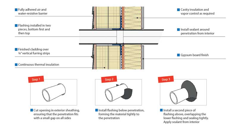
Lastly, there are other structural penetrations such as balconies, exposed slab edges, and intentional holes left to accommodate services like plumbing. These are major contributors to poor airtightness. Just like windows, each must be detailed to maintain continuity (Figure 3).
The pencil test
One of the best tools to begin the building envelope commissioning process during design is to perform a “pencil test” on a building cross-section or floor plans.
Take a pencil and, starting in the lower right-hand corner of the drawing, trace the line of each of the barriers moving upward along the walls, horizontally across the roof, back down to the footing, and horizontally across the lowest floor and back to the point of beginning. The areas where the pencil encounters anything other than a smooth, continuous plane is circled to identify potential areas of barrier interruptions. These include wall penetrations, fenestration openings, offsets,
or changes in materials.
Each circled area represents an architectural detail that is required to communicate how the barriers connect and remain continuous. Those details must be thought through and shown on the final construction drawings to ensure the barrier can indeed be constructed as continuous. It is no longer enough or appropriate to simply mention ‘continuous’ in a note identifying the barrier—it must be accompanied by an architectural detail.
Quality control during construction
The importance of the air barrier is more widely understood, but disconnect between design and installation is not always given the attention it deserves by project teams. Insufficient drawing details at transitions and intersections can result in breaks in the air barrier and increased air leakage across the building enclosure plane at the point of installation.
In some cases, the construction manager and subcontractors do not have a fundamental understanding of the air barrier. As a result, breaches in the air barrier due to difficult transitions are unidentified during construction, and subsequently repaired. However, instilling quality control methods during design and construction minimizes the risk of damage associated with a leaky air barrier.
First, consider full-scale, onsite mockups to illustrate and review details and conditions found in the overall project. This offers the installing contractor an opportunity to review the assembly, sequencing, and constructability of the various components. All participants can see and agree upon the critical details upfront and prior to large-scale assembly.
The lab test for a mockup is CAN/ULC 742 or ASTM E2357, Standard Test Method for Determining Air Leakage Rate of Air Barrier Assemblies (both acceptable under NBC, but the CAN/ULC test also involves temperature differentials, so it is preferred by Canadian designers). However, it should be determined before the mockup stage if those standards are being met.
Second, pre-installation meetings are a simple way to ensure co-ordination of all onsite workers. It is important to include not only the installing contractors for the air barrier, but also the tradespersons responsible for overlying components. Insist on a meeting where the wall air barrier, roofing, and waterproofing contractors discuss edge conditions and the overlapping of materials, potential time delays between the installation, and other co-ordination issues to ensure a continuous air barrier.
Sign up for our weekly newsletter
Construction Canada weekly newsletters give the latest AEC industry news for those who build, design, engineer, specify, renovate or operate in the built environment.
Related Products & Services

Read the Latest Issue