Canadian Museum for Human Rights: Design excellence and structural innovation at the Forks
By Neb Erakovic, M.A.Sc., P.Eng., Crispin Howes, P.Eng., and Terry Dawson, M.Eng., P.Eng.
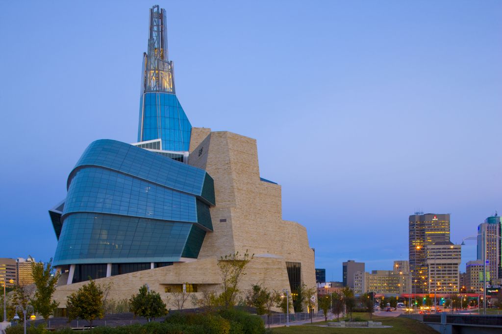
Located in the geographical centre of Canada at The Forks of the historic Red and Assiniboine Rivers in Winnipeg, the architectural design for the Canadian Museum for Human Rights (CMHR) was selected from an international competition that included 62 submissions from 12 countries. One of the largest judicial reviews in the country’s history, it stretched over 18 months and included three levels of detailed submissions.
Antoine Predock’s winning design draws inspiration from Canada’s natural scenery and open spaces. The museum is envisioned to be an iconic symbol—a magnificent and unique structure, showcasing a world-class experience that will be a true testament to the importance of Canada as both a nation and as an inspiring place for the wider human rights debate relating to the planet’s diversity.
Initiated in 2003 by CanWest founder, Israel Asper, to be the largest human rights institution and education centre in the world, the CMHR construction was made possible by a partnership that includes the Government of Canada. The Museums Act reads:
To explore the subject of human rights, with special but not exclusive reference to Canada, in order to enhance the public’s understanding of human rights, to promote respect for others, and to encourage reflection and dialogue.
Yolles, A CH2M HILL Company, was selected to provide structural engineering consulting services for the building. It completed this challenging task by collaborating with the architects to translate their vision of organic forms into rational structural component solutions tied together to create a building that is stable and constructible.
From the structural perspective, this project highlights the benefits and importance of modern tools and technology associated with three-dimensional modelling of complex geometric forms and development of interfacing details for building interwoven components; constructed using practically all common building materials, including steel, concrete, glass, and stone.
Complexity in form
The CMHR is one of the country’s first large projects of extreme complexity relying on interdisciplinary co-operation and construction to successfully achieve use of virtual models for real-time collaboration and interaction between various groups in different locations—as many as 40 companies located in eight cities in North America and Europe. The high-tech tools, combined with computer-generated models, were unconventional in the beginning, but quickly recognized as the essential elements in design and construction processes for this unique building and related precise details associated with various components and materials.


Commencing with the basic 3D visualization of the building, continuing through the preconstruction planning, quantity take-offs, procurement, and construction, virtual models proved to offer a complete package that helped clear unknowns, improve efficiencies, and mitigate potential risks. This new process implemented into a traditional industry proved to be a great success where, in many cases, traditional 2D documents would have proved to be inadequate.
![The assembly of primary programmatic zones. [CREDIT] Image courtesy Antoine Predock Architect](https://www.constructioncanada.net/wp-content/uploads/2014/06/Program.jpg)
The iconic architectural forms used by Predock’s team within CMHR resulted in significant structural complexity, including:
- large column free spaces;
- unconventional load paths;
- long cantilevers;
- delicate detailing of glass façades; and
- highly stressed connection points between steel forms and at concrete walls.
When it came to the translation of complex architectural geometry into structural solutions, the only way to advance the structural design was to break the structure into separate components. This allowed them to be modelled independently and to be sequentially integrated into the building’s overall structural scheme.
As a result of this process, the building structure can generally be considered as separate structural components tied to create the unique form. In many areas, the complex and unconventional geometry led to convoluted load paths between structural elements.
The basic design
The CMHR structure is generally composed of four base ‘Roots,’ radiating out from a central ‘Great Hall’ and ‘Garden of Reflection’ beneath a suspended ‘Mountain,’ ‘Cloud,’ and ‘Tower of Hope’. The 50-m (164-ft) tall ‘Hall of Hope’ atrium at the back of the building cuts into the Mountain and Roots like a canyon and houses circulation ramps between galleries.
![Schematics of diagrid Mountain trusses. [CREDIT] Image courtesy Yolles, A CH2M HILL Company](https://www.constructioncanada.net/wp-content/uploads/2014/06/Schematic.jpg) The Roots contain the functional spaces of the museum and are constructed of sloping, segmented, reinforced concrete walls. The Mountain contains the bulk of the exhibition spaces, and the Cloud encapsulates office spaces and a large atrium. Projecting above the Cloud roof, the Tower of Hope houses an observation gallery to provide visitors with a stunning view of The Forks, downtown Winnipeg, and the surrounding prairies. (All building components are reminiscent of natural forms, also incorporating icebergs and dove wings.)
The Roots contain the functional spaces of the museum and are constructed of sloping, segmented, reinforced concrete walls. The Mountain contains the bulk of the exhibition spaces, and the Cloud encapsulates office spaces and a large atrium. Projecting above the Cloud roof, the Tower of Hope houses an observation gallery to provide visitors with a stunning view of The Forks, downtown Winnipeg, and the surrounding prairies. (All building components are reminiscent of natural forms, also incorporating icebergs and dove wings.)
The unique Mountain exhibition galleries, curved Cloud façade, Tower of Hope spire, Garden of Reflection, and Hall of Hope ramps posed significant design challenges through use of structural steel frame interconnected with spatial concrete shells and multi-faceted curved glass façade. When an idea and design philosophy are transformed into a practical and constructible building, it takes the talents of all aspects of the industry and team collaboration to come together to deliver the finished product representing the original vision.
Form challenges and structural steel solutions
The Mountain consists of a seemingly randomly stacked array of five stone-clad closed steel forms of irregular shape suspended 18 m (59 ft) above ground floor. Initially conceived in reinforced concrete, use of structural steel framing was necessitated by the various design challenges, which included:
- highly stressed contact points between forms;
- large column-free spaces;
- significant form cantilevers;
- large openings in walls;
- sloping walls;
- eccentricity of stone cladding; and
- unconventional vertical and horizontal load paths.
![Shared super nodes with diagrid members between Mountain forms. [CREDIT] Images courtesy Yolles, A CH2M HILL Company, and Walters Inc.](https://www.constructioncanada.net/wp-content/uploads/2014/06/Node1.jpg)
Each two-storey Mountain wall consists of structural steel W-sections and corner circular hollow sections to form the primary diagrid wall trusses that span significant unsupported distances between concrete walls and steel columns. The diagonal and vertical elements within the diagrid wall trusses are positioned around wall openings to provide direct load paths down to supports, but also transfer lateral loads down the building with composite floor diaphragms distributing those loads across to supporting walls.
Parametric sensitivity analyses were conducted to assess the effects of changes in temperature, slab and wall cracking, construction sequencing and staging, and connection fixities. Optimizing the stacked diagrid wall truss member locations, designs, and connections with consideration to these parameters is complicated by their redistributive nature.
Another significant design challenge was the lower Mountain form cantilevers 16 m (52 ½ ft) over part of the Garden of Reflection. A disproportionately small 20-m (66-ft) back span required the floor diaphragms at the top and bottom levels of this form to act as a horizontal force couple. This provided supplemental resistance to the cantilever’s overturning.
The connection of cantilever to the concrete core walls also proved to be challenging, requiring complex tie-in connections at this material interface. The massive supported weight of stone cladding, heavily loaded exhibition and plant floors, upper Mountain, Cloud roof, and the Tower of Hope meant this form needed to be super-elevated at erection to ensure flat floors in the final condition. Extreme loads also require six 500 x 100-mm (20 x 4-in.) solid steel plates to be built up to form a solid 500 x 600-mm (20 x 23 3/5-in.) steel diagrid member. The design and construction of this cantilever form proved to be the project’s most challenging aspect.
![The zone of overlap between Cloud wings. [CREDIT] Photo courtesy Antoine Predock Architect](https://www.constructioncanada.net/wp-content/uploads/2014/06/Zone.jpg)
The Cloud
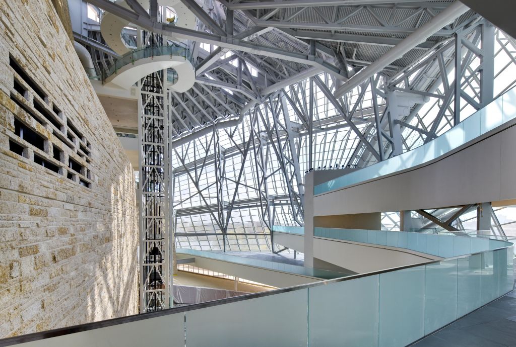
The glazed Cloud encapsulates the large central atrium, museum offices, and Garden of Reflection. The Cloud curvature is framed with a series of curved 610-mm (24-in.) diameter hollow circular steel pipes supported by raking built-up hollow steel columns that span more than 30 m (100 ft) from the Roots up to the Cloud roof.
Balcony-like partial perimeter office floors encircle the atrium at three levels, acting as diaphragms to provide lateral stability to the raking columns. Steel framing allows light into the Tower of Hope and practically unobscured panoramic views out. The underlying geometry consists of two overlapping cones discretized into faceted shards of layered glazed panels.
The Garden of Reflection
Located at the base of the Cloud atrium and Tower of Hope, the Garden of Reflection provided its own structural complexity. To provide a column-free space for the dark void of the Great Hall below and to support the Tower of Hope elevator hoist-way and spiral stair above, a two-directional, long-spanning, steel truss support system was used.
The Garden of Reflection’s framing, which supports still water pools and Basalt stone seating, floats between surrounding structural components (Hall of Hope walls and adjacent Roots) and sits on sliding bearings to prevent the attraction of significant compatibility forces. Behind the Garden of Reflection, circulation ramps, clad in backlit alabaster stone, link the museum exhibition spaces and fly through the Hall of Hope atrium—a 50-m (164-ft) high black concrete canyon.
These ramps, which are steel pony trusses up to 25 m (82 ft) in length, are highly irregular and susceptible to significant human-induced vibrations. Steel was the only viable solution for this complex series of pathways. As each ramp is unique in span and supports, a repetitive structural framing system was used to rationalize the fabrication and construction.
Temporary bracing
Owing to the prairie climate, it was anticipated the structure could experience temperature differentials of at least 30 C (54 F) before the building needed to be enclosed. Expansion joints were not possible within the interior due to the requirement for continuous diaphragms to resist wind loads and to hold sloping, cantilevered, and unbalanced parts of the building together. This meant locking the various steel components of the structure into the supporting concrete walls during construction would result in unacceptably high thermal restraint forces and potential damage.
![Long-span trusses below the Garden of Reflection. [FILE] Photo courtesy Smith Carter Architects](https://www.constructioncanada.net/wp-content/uploads/2014/06/Truss.jpg)
Temporary steel slip connections and slab separation strips were used to disconnect selected structural components during construction with temporary bracing introduced to maintain stability until the building was enclosed.
Advances in reinforced concrete design and construction
Four projecting roots at the building’s base were formed from vertical and inclined concrete walls that support sloping roofs. While the original design anticipated spatial forms to be double-curved surfaces, design evolved into segmented trapezoidal planes to rationalize truncated cones and to facilitate engineered formwork design. Some root walls are sloped up to 23 degrees from vertical, and are featured with faces finished in architecturally exposed, coloured, ‘shaggy’ concrete.
Shaggy concrete generally consists of pre-meditated poor concrete that emulates natural earthen surfaces such as exposed walls of sedimentary rock. The creation was closely developed with architects and the contractor to include methods to form, colour, pour, and finish concrete to create the desired appearance.
Floor diaphragms are important links between gravity- and lateral-resisting elements of any complex building structure, as they tie various elements to form a stable overall structural system. Floor diaphragms consist of reinforced concrete topping on steel deck and additional steel bracing beams where forces proved excessively high for thin slabs. A lack of detailed building code provisions for diaphragm analysis and design required Yolles to develop its own rational analysis and design process appropriate to the design of this essential component in an extremely complicated application with load paths difficult to visualize without the use finite element method (FEM).
![Hall of Hope’s ramps are clad in alabaster and lit by light-emitting diodes (LEDs). [CREDIT] Photo © Patrick Coulie Photography](https://www.constructioncanada.net/wp-content/uploads/2014/06/ramps.jpg)
- additional temporary shores;
- controlling the method steel erection;
- cambering of the structural steel frame;
- controlling the sequence and timing of concreting and installation of the building cladding components; and
- controlling the sequencing of construction for sections of the project.
Buildings built in the regions of extreme temperature variance, such as Winnipeg, require the designer to consider both the methods and schedule of construction since the distribution of forces and movements of the structure are affected by the sequencing and temperatures during. Regular buildings constructed about a central core experience reduced temperature effects as the building perimeter freely moves, the three cores of CMHR generate significant restraint forces as the structure is not free to move between the points of resistance.
Expansion joints were not possible for the building in its final configuration due to required continuity of floors and the building enclosure to hold sloping, unbalanced, and separated components, and to link them to the supporting concrete walls. A temperature differential in uncontrolled environment for the building in construction meant unlocking the steel frame into the supporting concrete elements to control connection forces. Steel connection slip joint details, slab separation strips, three mega shores, and secondary temporary bracing was introduced to partially relieve the potentially significant thermal restraint.
3D visualization and information-sharing
By now, the advantages and disadvantages of building information modelling (BIM) are well-documented in the building construction industry. However, at the time of CMHR’s design initiation, it was a relatively new technology that forced a cultural change for the design consultant teams.
![The CMHR is one of Canada’s first large projects of extreme complexity relying on interdisciplinary co-operation and construction to successfully achieve use of virtual models for real-time collaboration and interaction. There were as many as 40 companies located in eight cities in North America and Europe. [CREDIT] Photo © Patrick Coulie Photography](https://www.constructioncanada.net/wp-content/uploads/2014/06/CMHR-10.jpg)
For the complex, three-dimensionally curved and sloping geometric forms of this building Yolles developed a sophisticated workflow to capitalize on the best aspects of several software programs more common to the industrial, automotive, and aircraft industries. Starting with CATIA (i.e. Computer Aided Three-dimensional Interactive Application, by French company Dassault Systèmes) in 2004, and moving to a full Autodesk Revit model four years later, these building models were employed as contract documents, along with conventional 2D drawings.
Various components of the building such as the Roots, Mountain, Cloud, and Tower of Hope were broken out and individually translated from design concept into structural components that were manipulated back into the master BIM geometric model. Ultimately, the benefits of BIM were realized in 3D visualization, sharing of information for co-ordination, and clear contract documentation. BIM was clearly the best tool to manage the building’s structural complexity.
Lasting impression
In combination with reinforced concrete and glass, structural steel was used to overcome numerous design and construction challenges for the architecturally complex Canadian Museum of Human Rights superstructure. BIM was successfully used to model, document, and construct the building structure with various software tools used in analysis and design, visualization, and collaboration throughout all phases of the project.
A true team effort and the latest advanced technologies were the only feasible options to satisfy the challenges posed by this architectural vision. The resulting magnificent building will be a true testament to the importance Canada, as a nation, places on human rights.
Neb Erakovic, M.Sc., P.Eng. is a principal at the Toronto office of Yolles, A CH2M HILL Company. He specializes in design and management of structures with architectural complexity. Erakovic can be reached at neb.erakovic@ch2m.com.
Crispin Howes, P.Eng., is a senior associate in Yolles’ Toronto office. He specializes in advanced geometric structural engineering and heads the firm’s Studio for Progressive Modelling. Howes can be contacted via e-mail at crispin.howes@ch2m.com.
Terry Dawson, M.Eng., P.Eng., is an associate in Yolles’ Toronto office. He has experience in structural engineering in Canada, the United Kingdom, and New Zealand. Dawson can be e-mailed at terry.dawson@ch2m.com.
To read additional project details, click here.
Sign up for our weekly newsletter
Construction Canada weekly newsletters give the latest AEC industry news for those who build, design, engineer, specify, renovate or operate in the built environment.
Related Products & Services


Read the Latest Issue