Calgary’s Bow: An iconic skyscraper revisited
Images courtesy Foster + Partners
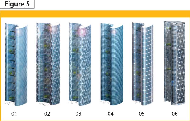
The alternative of using perimeter systems with closely spaced steel columns and variations of diagonal bracing schemes (and other hybrid systems, including ‘outrigger’ frames and ‘belt’ trusses) was studied before selecting this hybrid LFRS. (The architectural interpretation of alternate LFRSs is shown in Figure 5.) The curvilinear geometry of the floor plate, the cladding design, exterior and interior esthetics, space planning, daylighting, and economics of the steel framing scheme were primary decision-making factors for the building primary structural system.
The lateral system, and hence the atrium wall, was designed under wind, seismic, and thermal loads—wind being the governing case. Wind tunnel studies were performed to obtain the loads on the tower by creating a 1/400 scale model in a 600-m (1969-ft) radius environment. A separate test was performed on the atrium wall to determine the impact of wind loads on the long, unsupported atrium wall members. The resulting wind and seismic loads were applied to a finite element model.
In total, 180 ultimate limit states (ULS) and 64 serviceability limit states (SLS) load combinations were used. The deflection criteria considered were a maximum of h/400 at the top of the building, as well as a maximum inter-storey drift of h/350. For seismic loads, the inter-storey building drift was limited to h/40.
The gravity-load-carrying system was affected by the need to minimize the building’s height. Since the project is just south of the Bow River, Calgary’s urban guidelines required the building be low enough to avoid shadowing the river during the September equinox period. Consequently, a network of interior columns was added in a layout to ensure a depth of the floor beams below 485 mm (19 in.) underneath a composite floor slab construction consisting of a 75-mm (3-in.) concrete cover on 75-mm steel deck. High-strength steel—450 MPa (65 ksi)—was specified for all W-shape gravity columns above level 24 and for the heavy W360 members of the diagrid below this point.
The diagrid
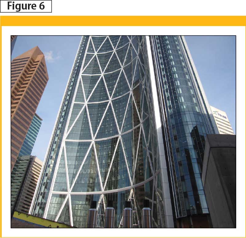
The atrium screen wall was a very dramatic element in the architectural design as it was exposed to all building users. Structurally, the wall was important as the diagonal grid was involved in completing or closing the perimeter lateral load-resisting system. Complicating the screen wall’s structural aspects was the large, unsupported length of the compression elements and the the screen wall’s tendency to attract gravity load from adjacent floor plates (Figure 6).
The design options included rectangular or triangular steel elements, along with round pipe (with possible concrete fill). Various studies were carried out on the three possibilities, including:
- esthetic impact;
- intrusion into the atrium;
- connection ease;
- support of a secondary mechanical/electrical/plumbing (MEP) system;
- perimeter curtain wall support;
- required fire-proofing system; and
- structural system constructability.
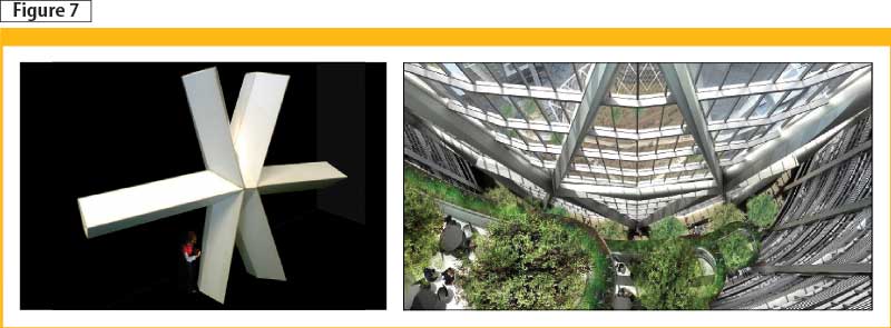
On a material basis, the round pipe with flange plate connections proved to be the least for structural cost, but with consideration of the other aspects (particularly esthetics), triangular elements were chosen. They appear in building information modelling (BIM) images in Figure 7.
The concepts of connections were initially developed by the structural design team through a series of hand-drawn sketches, and details then further refined and fully engineered by the steel contractor. Having dimensions of approximately 2.8 m (9.2 ft) in width and standing 4.2 m (13.8 ft) tall, the nodes are challenging not only to design, but also fabricate. Working with the thick plate involved preheating the elements before welding.
Internal stiffening plates were employed to contribute to an efficient load transfer through the node. This added to the system’s complexity, creating additional challenges for fabrication. The nodes were fabricated in the shop and then field-welded to the diagonal and horizontal diagrid members (Figure 8).
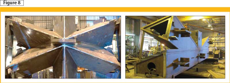
Images courtesy Walters
Using triangular built-up sections had its challenges—in the modern engineering era with computer-aided design (CAD) tools used extensively, these sections, nodes, and connections needed to be designed ‘by hand.’ The team had to go back to first principles in engineering to design these structural elements.
Construction logistics
Other aspects of the Bow’s construction brought unique challenges requiring creative problem-solving.
Top-down below-grade construction
Since the project’s design and construction schedule requirements had an aggressive timeframe, the client decided to bid the structural steel with a unit price contract based on schematic design phase documents. This design was based on a six-storey basement being constructed of reinforced concrete with the structural steel commencing at the ground floor level. Decisions by the project and construction managers led to the incorporation of structural steel to start from the raft foundation and with the concrete basement framing following after the steel was erected at grade (Figure 9).
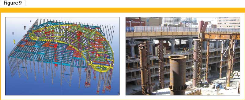
The steel was also extended most of the north block to provide an ‘umbrella’ to assist in the structural steel erection of the tower over the deep basement. The intent was for the tower steel to proceed above, while the slower-paced reinforced concrete basement backfilled off the main critical path schedule.
To achieve this ‘top-down’ construction, the lowest lifts of columns were augmented with tie down anchors into the raft design for the lower level floors. Added bracings located within the basement area were reinforcement to support the building until the permanent below-grade shear walls and ground-floor diaphragm could be constructed. In some cases, this temporary bracing was embedded within the final shear wall construction.
Sign up for our weekly newsletter
Construction Canada weekly newsletters give the latest AEC industry news for those who build, design, engineer, specify, renovate or operate in the built environment.
Products & Services


Read the Latest Issue