Best practices for masonry wall systems and insulation
Moisture vapour retarders
Placement of a vapour retarder depends on several factors. Vapour generally flows from high to low pressure—high pressure being warm air holding more moisture, compared to cool air holding less moisture. In northern climates, the vapour retarder typically goes on the ‘warm-in-winter’ side or inside, while in the south, it goes on the outside.
Current practice utilizes modelling software such as WUFI to make detailed hourly simulations of moisture migration and accumulation over multiple annual cycles to assess designs and predict performance. All building materials, such as gypsum board or brick, absorb water, hold it, and then release it as conditions change. WUFI analysis takes those dynamic characteristics into consideration. Section 1405.3, “Vapour Retarders,” of the International Building Code (IBC) provides guidance on the use of vapour retarders in different climate zones.
When vapour-retarding facers are part of the stud cavity insulation, its flame spread rating must also be considered. In Type 1 and 2 construction, facer flame spread must be less than 25. In Type 3, 4, or 5 construction, facer flame spread may be above 25.
Drainage
Water gets into a cavity wall through the brick veneer, which is normal and expected. Getting water out of a cavity wall involves the installation of multiple drainage planes, requiring numerous products including mortar dropping protection, through-wall flashing, and weep vents. Water also penetrates adhered masonry walls, and their proper design requires a WRB, drainage plane, and weep screed.
A complete wall design provides multiple pathways for drainage, does not allow the water to build up in the wall, and enables air to circulate to enhance drying. A reliable, high-performance wall system also has redundancies built in so if one aspect of the wall is challenged, there is another to back it up.
To keep weep holes open, mortar-dropping protection must be installed. With some proprietary three-dimensional, trapezoid-shaped porous fibre matrixes, falling mortar is suspended at different levels above the flashing, making it nearly impossible to accumulate a complete drainage block and thus keeping the weep holes open.
Weep holes used to be simply an open head joint at the base of the wall, but they allow a path for insects and debris to get in. Rope wicks allow water to leave the cavity, but they do not let air circulate. Rigid inserts preserve the opening and let water out and air in, but they may not fit the joint tightly or protect the opening well.
Some weep opening devices are both compressible and expandable, so they compress into the head joint and expand to fill irregularities. This type of a weep vent is a simple mesh tight enough to prevent insects and debris from getting in, but open enough to let water drain and air circulate.
Flashing systems
In cavity walls, through-wall flashing is installed at the bottom of the wall to catch water and direct it out. Water drains down the air barrier/WRB layer behind the ci or down the face of the insulation to the bottom of the cavity, where it is directed across the shelf angle or foundation out of the wall by through-wall flashing.
Traditionally, masonry cavity walls have often employed field-assembled through-wall flashing. However, a newer, field-proven alternative is an integrated flashing system, which comes preassembled with all necessary components, including the membrane, termination bar, drip edge, and a drainage mat with weep tabs—a component often omitted entirely when field-assembled. One-piece, 355-mm (14-in.) high corners and end dams are also available to complete the system. With field assembly, all these components must be provided at the same time by different suppliers, and it takes experienced professionals to assemble the flashing system correctly.
Since flashing failure is one of the primary causes of water damage, it is vital these components be installed correctly in every detail throughout the building. However, with current labour shortages, finding installers with enough experience may be a problem. Factory assembly of the flashing system in controlled conditions eliminates most of the variability of field installation and allows less experienced professionals to create leak-free installations. Takeoff services and custom cutting for wall openings can also be used to speed installation.
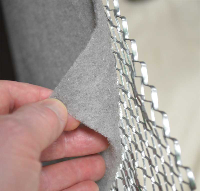
In adhered masonry walls, a through-wall flashing is unnecessary. Instead, a weep screed is installed at the bottom of the wall, a minimum of 101 mm (4 in.) above grade (Uniform Building Code [UBC] Section 4706 [e], “Exterior Lath: Application of Metal Plaster Bases”). The WRB is installed shingle-fashion so it drapes over the screed flange to allow water to run down the barrier and out of the screed weep holes. A drainage plane between the lath and WRB is necessary to ensure moisture can run down the WRB and air can circulate behind the lath to dry the wall. Products combining a factory-assembled metal lath and drainage plane in one system can significantly cut installation time compared to installing the drainage plane and lath separately. They also provide a mortar break to prevent mortar bridging between the lath and WRB, so the wall can drain and dry quickly and completely.
Sign up for our weekly newsletter
Construction Canada weekly newsletters give the latest AEC industry news for those who build, design, engineer, specify, renovate or operate in the built environment.
Related Products & Services

Read the Latest Issue