Balancing building science and roof design
Roof membranes as air barriers
In many respects, air barriers and roof membranes have much in common. Roof membranes require serious attention to terminations, penetrations, and flashings. Air barriers must be approached the same way, the goal being to prevent movement of air up into the roof system.
Air barriers often consist of a roll good, seaming tapes, caulks, and coatings. It is common to see spray-applied foam used to close large holes and gaps, followed by a coating and tapes to transition to the roof membrane.
While this is a common practice, questions still arise on how to design and install an effective air barrier system. The general misunderstanding of the concept of an air barrier and its purpose also significantly contributes to confusion on specifying these systems.
Air barrier basics
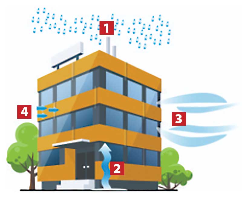
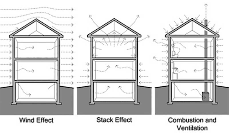
The primary function of an air barrier is to prevent or restrict air leakage through a building’s envelope. Air barriers are intended to control air flow from the exterior to the interior of a building, as well as from the interior to the exterior of a building.
An air barrier needs to be installed continuously on all sides of a building; an air barrier should “wrap” the entire building thermal envelope. For an air barrier to function properly, it should:
∞ meet permeability requirements;
∞ be continuous when installed;
∞ accommodate dimensional changes; and
∞ be strong enough to support the stresses applied to it.
An air barrier is not a single product or material. Rather, it is a combination of materials assembled and joined together as a system to provide a continuous barrier to air leakage through the building envelope.
An air barrier’s effectiveness can be greatly reduced by openings and penetrations, even small ones. These openings can be caused by poor design, poor workmanship, damage from non-roofing trades, improper sealing and flashing, mechanical forces, aging, and other forms of degradation.
The National Research Council of Canada (NRC) collected research data illustrating how even small openings can affect overall air leakage performance. For example, only about 0.3 L (0.08 gal) of water will diffuse through a continuous 1.2 x 2.4 m (4 x 8 ft) sheet of gypsum board during a one-month period, even though gypsum board has a high permeance.
However, if there is a 25 mm (1 in.) square hole in this same sheet of gypsum board, about 28.4 L (7.5 gal) of water can pass through the opening because of air leakage. This example illustrates how air leakage can cause more moisture-related problems than vapour diffusion.
Air barrier versus vapour retarder
When discussing air barriers, roofing membranes, and the building envelope, another important topic comes to mind: vapour retarders. There is often confusion between air barriers and vapour retarders. The purpose of a vapour retarder is to minimize or reduce water vapour diffusion into a low-slope roof or wall system. In other words, it is used to prevent the formation of condensation in a low-slope roof or wall system.
A vapour retarder is often called a “vapour barrier” and this contributes to getting the terms mixed up. Interestingly, model building codes in the U.S. use the term “vapour retarder,” yet confusion still exists. Canadian codes use the term “vapour barrier.” A lack of consistency does not reduce confusion.
Generally, a vapour retarder is used where a building’s interior humidity conditions are expected to be relatively high, and the building is in a cold climate. A vapour retarder is commonly installed on the warm (interior) side of a roof or wall. In a low-slope roof assembly, the vapour retarder is normally installed under the primary roof insulation.
Therefore, one will often see it installed directly on a roof deck (such as a concrete or wood deck) or on a continuous substrate (such as gypsum board or wood panels) installed directly over a metal deck. Conversely, in warm, high-humidity geographic locations, vapour retarders are installed on, or near, the exterior side of roofs and walls of air-conditioned buildings.
Sign up for our weekly newsletter
Construction Canada weekly newsletters give the latest AEC industry news for those who build, design, engineer, specify, renovate or operate in the built environment.
Products & Services


Read the Latest Issue