A guide to field notching and drilling LVL and glulam
Horizontal holes
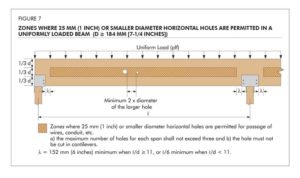
Like notches, holes in an LVL beam reduce the net section of the beam at the hole location and introduce stress concentrations. This causes a reduction in the beam capacity. For this reason, horizontal holes in LVL are limited in size and location to maintain the structural integrity of the beam. Figure 7 (page 42) shows the zones of a uniformly loaded beam in simple or multiple spans, where the field drilling of holes may be considered. The requirements given consider the effect of the horizontal hole on the shear and moment capacities of an LVL beam and may be applied to multiple-piece built-up LVL beams.
APA Technical Note, Effect of Large Diameter Horizontal Holes on the Bending and Shear Properties of Laminated Veneer Lumber, Form V900, provides additional engineering guidelines where larger horizontal holes than those specified here cannot be avoided in design.
A 25-mm diameter or smaller hole may be cut at the middle 1/3 of the beam depth anywhere along the span, except for the area within 152 mm of clear distance between the face of the support and the nearest edge of the hole (Figure 8), provided the following conditions are all met:
• the beam is at least 184 mm in depth;
• the beam is subject to uniform loads only;
• the span-to-depth ratio is at least 11;
• the maximum number of holes for each span is limited to three;
• the horizontal spacing must be a minimum of two diameters clear distance between adjacent holes based on the diameter of the larger
hole; and
• the hole must not be cut in cantilevers.
If l/d of the beam is less than 11, a 25-mm diameter or smaller hole may be cut in accordance with the provisions listed above except the location of the hole must maintain a clear distance between the face of the support and the nearest edge of the hole of at least 1/6 of the span (Figure 9).
Field-drilled horizontal holes must be employed for access only and must not be used as attachment points for brackets or other loadbearing hardware unless specifically designed as such by an engineer. Examples of access holes include those used for the passage of wires, electrical conduit, small-diameter sprinkler pipes, fibre-optic cables, and other small, lightweight materials. For oversized LVL beams, the guidelines given above may be relaxed based on an engineering analysis. When holes are required to be drilled outside the allowable zones, an engineering analysis must be conducted and approved by an engineer.
Regardless of the location, holes drilled horizontally through a member must be positioned and sized with the understanding the beam will deflect (creep) more over a period of time under in-service loading conditions. This deflection could overstress supported equipment or piping unless properly considered.
Vertical holes
Whenever possible, avoid drilling vertical holes through LVL beams unless the beam width is at least 89 mm (3.5 in.). Prior to drilling any vertical holes, an engineer must be consulted. Use a drill guide to minimize ‘wandering’ of the bit as it passes through knots or material of varying density and to ensure a true alignment of the hole through the depth of the beam. The vertical hole must be centred in the beam width.
As a rule of thumb, vertical holes drilled through the depth of an LVL beam cause a reduction in the capacity at that location directly proportional to the ratio of 1.5 times the diameter of the hole to the width of the beam. For example, a 13-mm hole drilled in an 89-mm wide LVL beam would reduce the beam capacity at that section by approximately 22 per cent ([13] (1.5)/89).
Holes for support of suspended equipment
Heavy equipment or piping suspended from LVL beams must be attached such that the load is applied to the top of the beam to avoid inducing tension perpendicular-to-grain stresses. Any horizontal holes required for support of significant weight, such as suspended heating and cooling units or main water lines, must be located above the neutral axis of the beam and in a zone stressed to less than 50 per cent of the allowable bending stress. The beam capacity must be checked for all such loads to ensure proper performance.
Protection of field-cut notches and holes for LVL and glulam
Frequently, LVL and glulam beams are provided from the manufacturer with the ends sealed by a protective coating. This sealer is applied to the end grain of the LVL and glulam beams to retard the migration of moisture in and out of the beam ends during transit and jobsite storage. Field cutting a notch in the end of a beam can change the moisture-absorption characteristics of the LVL/beam at the notch location. This can result in seasoning checks or localized splitting developing at the root of the notch. To minimize this possibility, all notches must be sealed immediately after cutting using a water-repellent sealer. Sealing other field-cut locations as well as field-drilled holes is also recommended. These sealers can be applied with a brush, swab, roller, or spray gun. Find additional resources for free download at www.apawood.org.
 Borjen “BJ” Yeh, PhD, PE, is technical services director for APA – The Engineered Wood Association. He has been with APA for 30 years. Yeh earned his M.S. at Iowa State University and PhD at University of California, Berkeley. He can be reached at borjen.yeh@apawood.org.


