A guide to field notching and drilling LVL and glulam
Laminated veneer lumber
Most LVL products are used as beams and headers loaded parallel to the gluelines. Drilling, tapering, or notching LVL reduces the net section and may introduce stress concentrations at the notching or drilling location. Therefore, a cautious approach to field modifications is vital. Note, LVL is a proprietary product and the notching and drilling requirements specified by the manufacturer must be followed and supersede the general recommendations that are provided hereinafter.
Notching
Notching of LVL beams must be avoided whenever possible, especially on the tension side of a member. Tension-side notching of LVL beams is not recommended except at end bearings, and then only under specific conditions. The notching of LVL beams on the tension side results in decreased strength caused by stress concentrations developing around the notch and a reduction of the net cross-section resisting the bending and shear forces. Such notches induce perpendicular-to-grain tensile stresses, which, in conjunction with horizontal shear forces, can cause splitting along the grain, typically starting at the inside corner of the notch. Stress concentrations due to notches can be reduced by using a gradually tapered notch configuration in lieu of a square-cornered notch. Rounding the square corner of a notch with a radius of approximately 13 mm is also recommended to reduce stress concentrations in these areas.
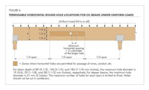
LVL beams illustrated in Figure 6 (page 40) are assumed to be simple span subjected to uniform loads. All equations and notching guidelines are presented using the same assumptions. If this information is applied to continuous or cantilevered beams, it must be used with extreme caution and only based on rational engineering analyses.
Where LVL beams are notched at the ends for bearing over a support, the notch depth is recommended to not exceed 1/10 of the beam depth (Figure 6[e]). Within the limitation given above, the shear stress at the notch can be calculated in accordance with Figure 6(e). For notches on the compression side, a less severe condition exists and equations for the analysis of the effects of these notches are also given in Figure 6. The equations given are empirical in nature and were developed for the conditions shown.
The notching provisions are limited to uniformly loaded simple-span beams. The notches shown in Figure 6 occur in areas of high shear and lower moment. For this reason, the design equations given are shear equations.
When necessary to cut a small notch in the top of an LVL beam (in the compression side) to provide passage for a small-diameter pipe or conduit, the cut must be made in an area of the beam stressed to less than 50 per cent of the allowable bending stress.
The net section in this area of the beam must be checked for shear and bending stresses to ensure adequate performance.
All field notches must be accurately cut. It is important to understand improperly cut field notches may reduce the capacity of a beam and cause serious structural failure. Avoid over-cutting at the corners of the notch. Drilling a hole in a member at the interior corner of a notch as a stop point for the saw blade provides both a rounded corner and minimizes over-cutting at the corner.
It must be recognized the top of an LVL beam might not always be stressed in compression and the bottom of an LVL beam might not always be stressed in tension. For example, if the LVL beam is designed for wind uplift, the top of the LVL will be stressed in tension and the bottom of the LVL will be stressed in compression. In this case, the recommendations given above must be applied accordingly. Further, when evaluating the effect of notching, the shear force within a distance from supports equal to the beam depth must not be neglected, as typically permitted by the design of rectangular wood members in accordance with the Wood Design Manual.

