A comprehensive scrutiny of building enclosure design and construction
Reviewing details
The drawings should be reviewed (in conjunction with the specifications) in the schematic design, design development, and construction documentation phases. The evaluation would focus on determining if a sufficient number of details have been provided for most/all building envelope transitions, as missing or poor detailing can spiral down to misleading pricing, incorrect shop drawings, and improper execution at the project site (Figure 3). This culminates in poorly performing buildings with an increased risk of leaks and maintenance costs.
Building envelope transitions between assemblies should be assessed for continuity of fundamental control layers to ensure durable detailing of the building enclosure is achieved. These control layers, in order of importance, should something fail, are:
- water;
- air;
- thermal (insulation); and
- vapour.
Generally, discontinuity in the water control layers have an immediate impact or cause the most deterioration, followed by air, and then thermal and vapour issues, which may be tolerable to a degree, with potentially a lesser expected level of deterioration.
Achieving continuous control layers is a challenge in both the design and construction stages, as water and air can enter buildings in multiple ways and concerns surrounding thermal bridging are still prevalent, all of which lead to failures and occupant discomfort.
Durable detailing
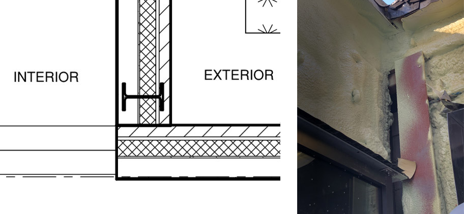
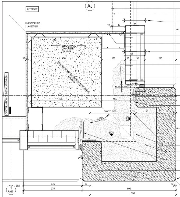
Durable detailing in the contract documents is the first step in constructing a low-maintenance, durable, and energy-efficient building. Figure 4 illustrates potential constructability and durability concerns, which can arise during the design phase. While the intent in this design is to provide a well-insulated precast assembly, with membrane transitions to adjacent windows, it would be infeasible to install spray foam to provide continuity of the thermal barrier due to the location of the transition (behind a column) and shape of the concrete. Additionally, direct membrane transitions to typical window-wall framing are not durable due to the profile of the frames. An alternate approach such as a combination of membrane, metal flashings, and backer/rod and sealant would maintain air barrier continuity from the back of the window frame to the precast concrete.
Window location
Something as simple as window location can significantly impact a building envelope’s thermal performance and reduce the overall performance of an insulating window or wall assembly by 25 to 50 per cent. If the thermal plane of the insulating glass unit [IGU] does not line up with the thermal control layer in the surrounding wall, thermal flanking around the perimeter of the transition reduces the effective thermal performance of both assemblies. The greater the offset, the greater the impact. Figure 5 illustrates the thermal flanking phenomena by the sharp changes in direction of the temperature isotherms at the transition. In this example, the energy model assumed windows would have an effective U-value of 0.357 (~R-2.8), and spray foam insulated precast concrete walls U-value of 0.038 (~R-26). However, due to the offset in thermal planes, the modelled U/R-values were U-value 0.562 and 0.071 (R-1.78 and R-14) respectively, a roughly 35 and 46 per cent reduction. If such discrepancies between assumed and calculated U/R-values are not identified in the design stage, the as-built performance of the constructed facility will not meet the planned energy use targets.
Isometric details
As building materials and transitions become more complex, the importance of thorough detailing is more critical. Contract document and shop drawing details should provide as much information as possible with respect to materials and continuity of control layers—comprehensive detailing equals fewer unknowns during construction for contractors, leading to lesser impromptu transition details. Where two-dimensional detailing may be insufficient to fully illustrate continuity in contract document, isometric/three-dimensional detailing is recommended (Figure 6). Areas/details where isometric drawings are recommended are:
- intersection points of three different planes, such as a terrace parapet crossing with a curtain wall;
- continuity of expansion joints between different assemblies and planes like roof-to-wall-to-foundation; and
- where complex drainage/venting paths are required, such as skylight transitions to curtain walls.
Sign up for our weekly newsletter
Construction Canada weekly newsletters give the latest AEC industry news for those who build, design, engineer, specify, renovate or operate in the built environment.
Related Products & Services

Read the Latest Issue