Older Masonry Buildings: Benefits, risks, and design approaches for adding interior insulation
By David De Rose, P.Eng., Sarah Gray, P.Eng., and Kim D. Pressnail, PhD
Canada’s historical buildings present a dilemma in terms of today’s performance expectations. They have little to no wall insulation, and covering their beautiful exteriors with insulation is either undesirable or prohibited by local authorities, since many of these buildings are designated heritage properties with required façade protection.
Adding interior insulation is the obvious solution. However, such retrofits can compromise the wall assembly’s durability by increasing the moisture content across the wall section. Before adding interior insulation, therefore, it is important to carefully assess the risks and test the proposed design approach.
This article explains the risks caused after adding interior insulation to these walls, details how the risks can be managed, and outlines practical design approaches.1
structure has heritage designation, and interior insulation retrofits were considered as part of the recent industrial-to-commercial adaptation.
An insulation primer on solid masonry building
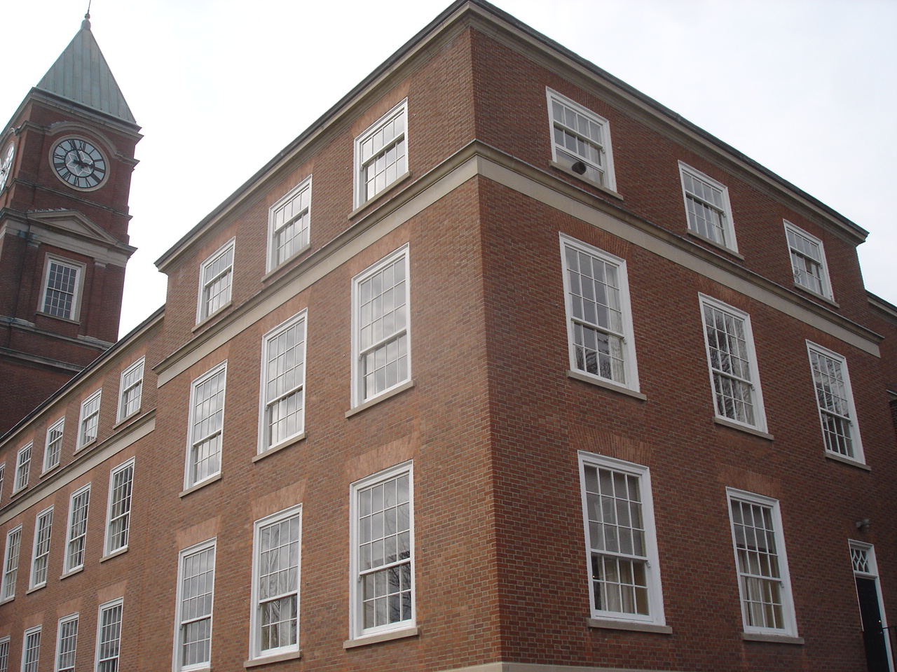
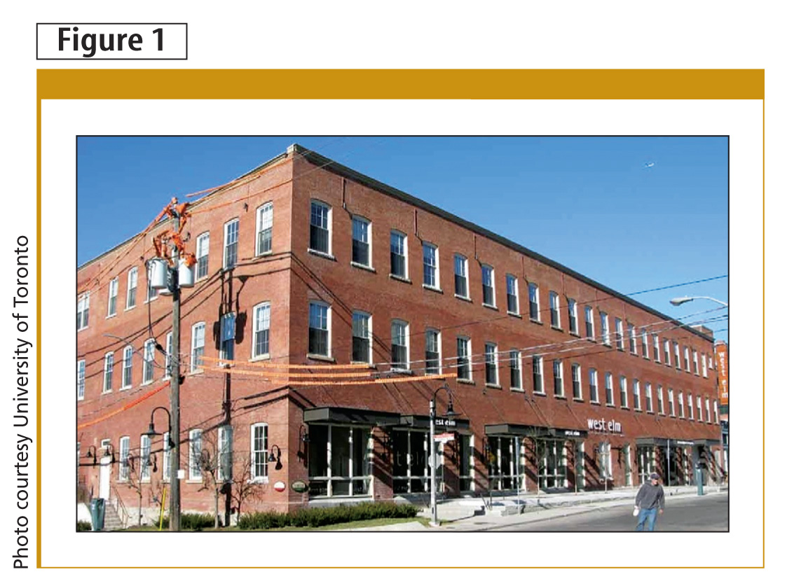
Buildings with thick, solid brick or stone walls rely on the mass or thickness of the masonry to resist water penetration and provide a buffer between interior and exterior environments (Figure 1). Buildings constructed before World War II, many of which are now designated heritage properties, were designed when energy was inexpensive. Insulation may not be provided at the exterior walls, since energy was relatively cheaper than the cost of providing insulation. As a result, these buildings have little thermal resistance and drafty exterior envelopes (Figure 2).
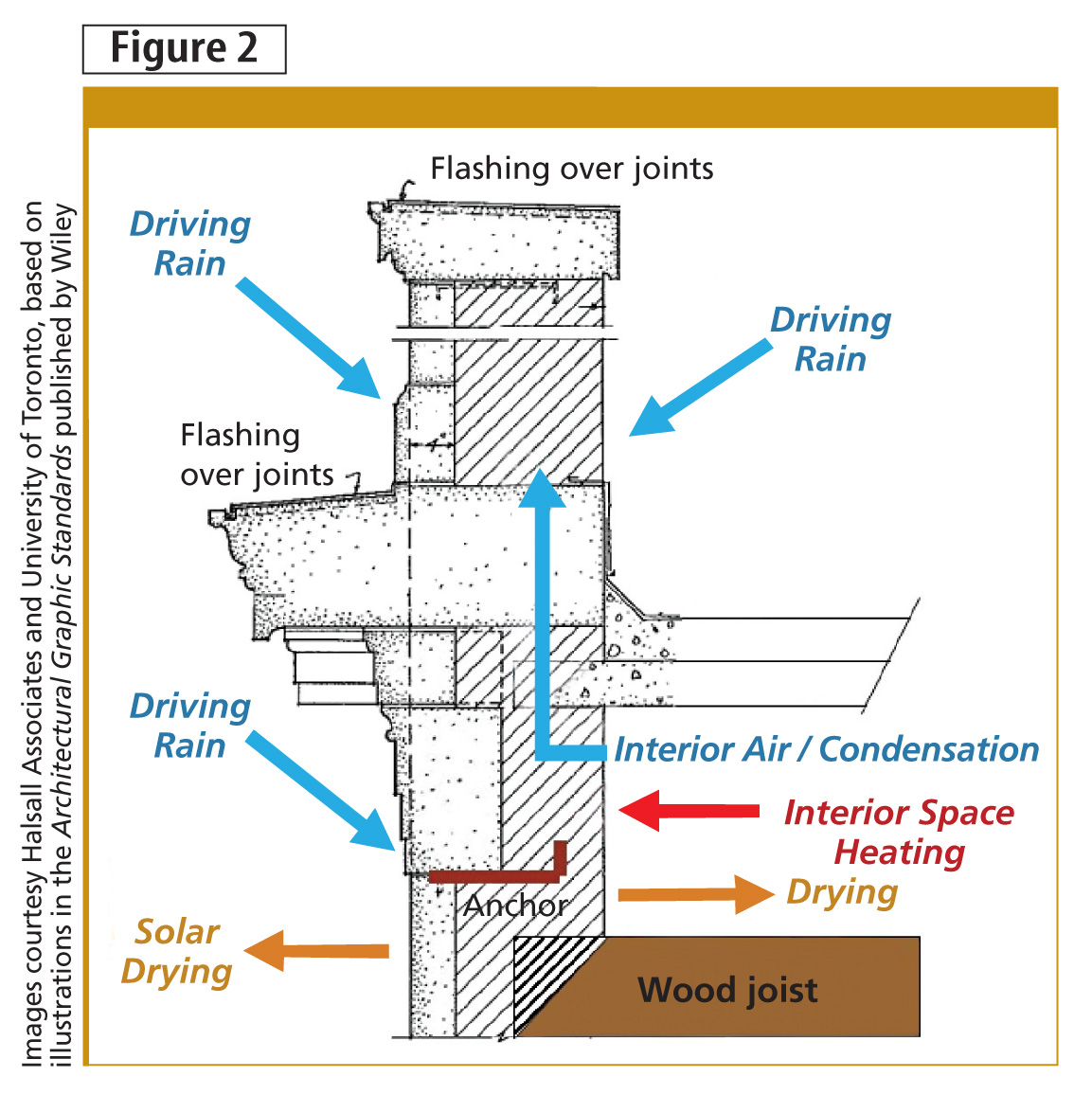
By contrast, masonry-clad buildings from the 1950s to ’70s are typically solid-wall (i.e. brick over concrete block) or non-drained veneer construction. Walls from this era may have ‘beadboard’ insulation (i.e. expanded polystyrene [EPS]) between the interior concrete block and drywall, batt insulation between studs inboard of the block backup, and/or beadboard in the air space between the exterior brick and block backup.
The insulation value provided is usually not at today’s performance levels, but, unlike solid masonry buildings, some of these mid-century structures are perfect candidates to be over-clad with an exterior insulation and finishing system (EIFS).
An optional air/moisture control layer and insulation is adhered over the brick, then covered with EIFS lamina and a finish coat or other cladding to improve durability and provide a fresh appearance (Figure 3). These over-clad systems provide better energy performance, more airtightness, and improved water resistance. This approach is suitable to buildings without heritage designation and when changes to exterior appearance are tolerated or even desired.
Understanding the risk of adding insulation
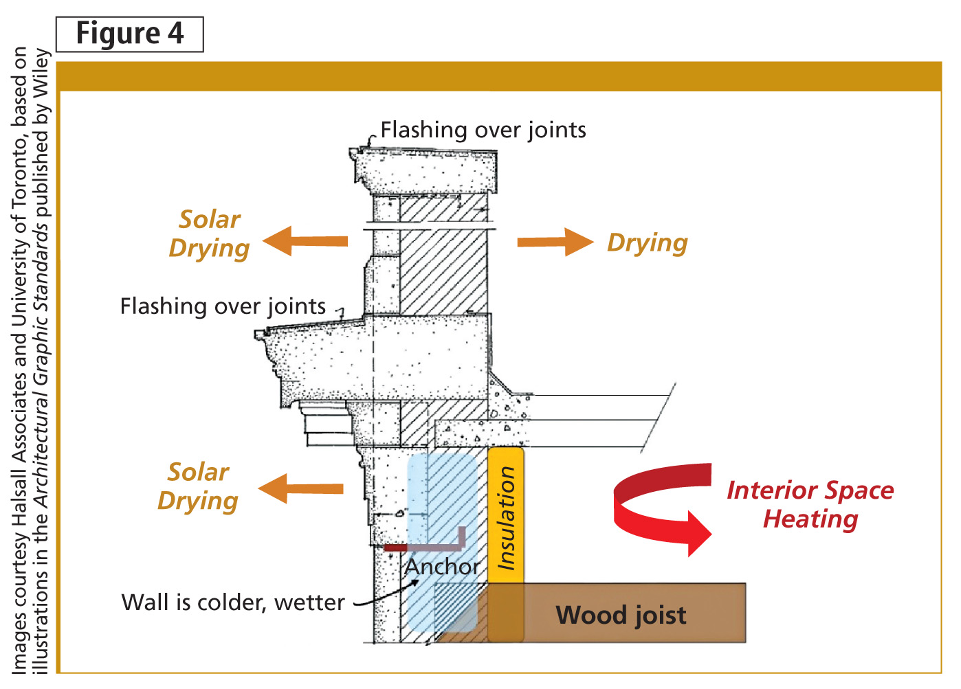
Insulating on the inboard side of solid masonry walls makes them colder during winter, since they are no longer exposed to heat losses from the interior. Since the wall is still exposed to rain year-round, solar heating or natural wicking can drive moisture within the brick toward the interior, thereby raising the masonry’s moisture content. Applying closed-cell, medium or high-density sprayed polyurethane foam (SPF) insulation also reduces the ability for walls to dry to the interior, because the foam is an effective vapour control layer.
When walls are colder, they take longer to dry. Reduced drying in winter means brick and mortar can reach critical moisture contents that can cause damage during freeze events. Other materials within the masonry can also deteriorate (Figure 4).
While the masonry may have previously performed with little visible deterioration, changing the environment within the walls after adding interior insulation may cause or accelerate deterioration, the type and rate ultimately depending on:
- physical characteristics of the masonry and other embedded materials;
- amount of moisture to which walls are exposed; and
- how much drying occurs before a freeze event.
However, many old masonry buildings have an existing level of exterior façade deterioration that correlates to areas of rainwater concentration caused by inadequate architectural detailing (e.g. insufficient drip edges) or lack of routine maintenance (e.g. leaking eavestroughs or downspouts). Existing deterioration and poor detailing should be repaired before adding interior insulation, since the insulation could contribute more moisture to wall, increasing deterioration risk.
If the masonry is getting too wet from driving rain exposure, designers could reduce water absorption by repointing the mortar joints and applying a breathable water-repellent sealer to the brick and mortar. Another possibility would be to provide overhanging flashings/drip edges to shed water off the walls.
Limit states design
Building scientists and engineers use computer software, physical testing, and/or onsite data acquisition to assess deterioration risks that may result after installing interior insulation. The general approach includes:
- assigning ‘loads’ to which the walls are exposed (e.g. rain, solar heating, heat losses from inside, and freezing temperatures);
- checking the wall materials’ resistance (i.e. physical properties); and
- comparing applied loads to the material resistance.
Comparing loads to resistance is referred to as a ‘limit states approach.’ While engineers have long been using limit states design for structural framing systems, adapting it for insulation retrofits has only recently been the subject of research and testing. With the limit states approach, the resistance of materials in the wall must be greater than the loads applied to the materials.
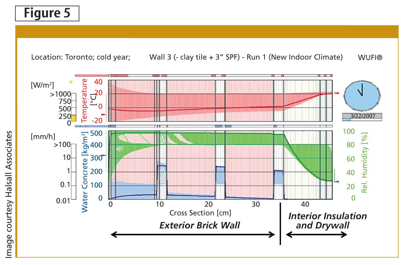
For masonry walls, wetting, freezing, and drying potentials can be simulated with software or established by direct measurement. These parameters are included in a computer model using hygrothermal analysis software that exposes the wall to a range of climate exposures (i.e. ‘loads’) and predicts these loads’ effects through the wall’s thickness. The results can point to locations within the wall where moisture content would exceed material ‘resistance’ and result in freeze-thaw deterioration, metal corrosion, or wood-rot thresholds or limits (Figure 5).
Assigning loads on specific walls
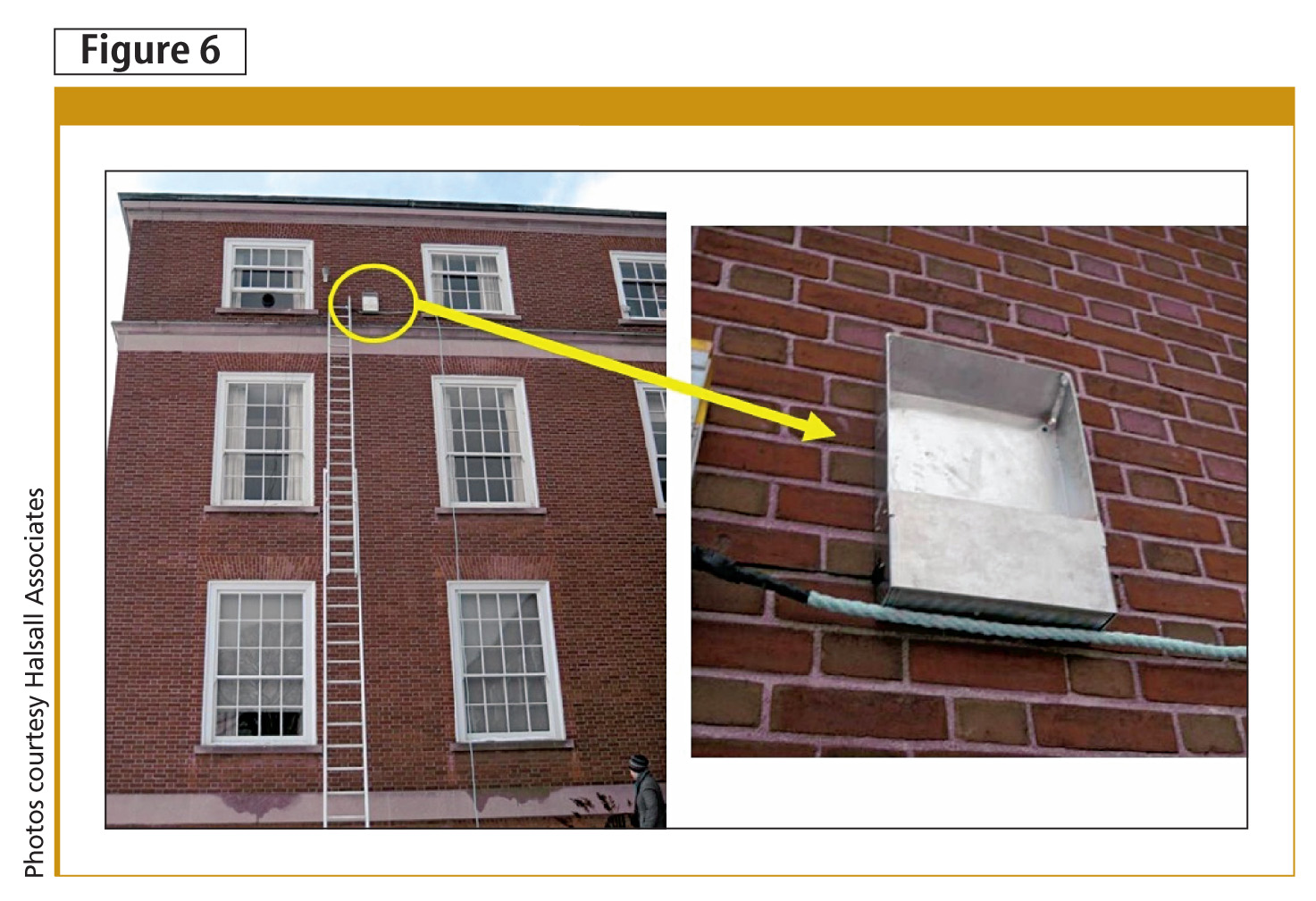
Climate data published by government agencies are specific to a city or region. A building’s particular exposure to rain and wind may vary significantly from published averages, depending on such influences as adjacent buildings or local topography. While published climate data can be used in preliminary analysis, a building’s specific exposures could be refined by information collected onsite. For example:
- exposure to and amount of rain-wetting can be measured by installing driving rain gauges to the façades (Figure 6);
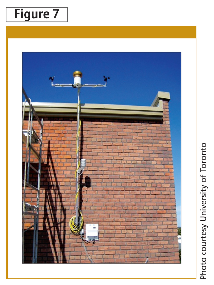
- weather stations record temperatures, wind direction, and exterior relative humidity (RH) (Figure 7); and
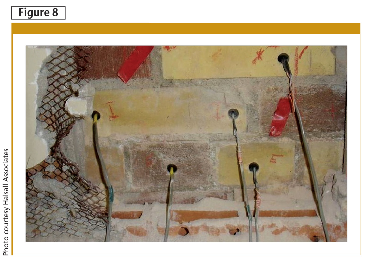
- in-wall sensors could record temperature and RH in test areas with and without insulation (Figure 8).
Confirming resistance to deterioration
Masonry’s resistance to deterioration is related to the amount of water it absorbs—more water within brick pores typically means greater risk for deterioration after exposure to freezing cycles. The wall may experience more time at moisture levels supporting freeze-thaw deterioration of the brick after insulating it than did in the past.
Visual review of parapets and chimneys—wall components typically exposed to water and freezing—can provide preliminary indications of how other wall areas might perform once they are made colder by interior insulation. If parapets or chimneys are deteriorated, this might indicate the brick is porous and susceptible to degradation. Material testing to establish brick’s water absorption potential, regardless of visual condition, should be considered during preliminary retrofit design. The type and extent of testing depends on the project team’s timelines and available budgets.
Simple tests
- Water uptake: The amount of time it takes brick to absorb water from a RILEM tube—a plastic tube that holds a pre-calibrated amount of water against the brick surface—or the absolute amount of water absorbed over a specified time is recorded, then compared to measurements from bricks with known properties. Results are used to anecdotally classify brick as “very absorptive,” “average absorption,” or “less absorptive” in comparison to other bricks.
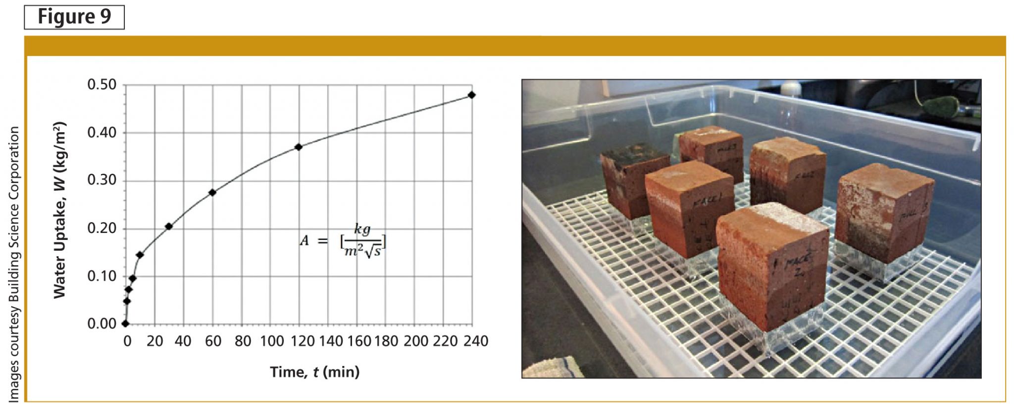
- A-Value (water absorption co-efficient): The European Committee for Standardization (CEN) 89 N 370 E test quantitatively measures the rate at which kiln-dried brick absorbs water. The A-value is the slope of the initial (steeper-sloped) portion of the water uptake curve and characterizes moisture transport (Figure 9).
- Free water saturation: The amount (by mass) of cold water absorbed by a brick fully immersed for 24 hours is determined and reported as a percentage of the brick’s initial dry mass (C-value per Canadian Standards Association [CSA] A82, Fired Masonry Brick Made from Clay or Shale). The free-water-saturation moisture content (Sf) is obtained by multiplying the 24-hour cold-water soak moisture content by the brick’s bulk density. This is the amount of water a brick can ‘naturally’ store (without external applied forces).
- Saturation co-efficient: The same bricks used to determine the C-value are immersed in boiling water for five hours to determine the mass of water absorbed (B-value). The ratio of C/B is the saturation co-efficient. CSA explains C/B as the ratio of “easily filled” pore space (in cold water) to “total fillable” pore space (boiling water).
More detailed tests
- Vacuum saturation: In the aforementioned ‘simple’ tests, some brick pores may be filled with air, which would decrease potential for water absorption. For this test, air in brick pores is evacuated under a vacuum before the brick is immersed in water. The result is reported as ‘maximum saturation’ (Smax), since it reports the maximum amount of water the brick can store (with external forces and condensation within pores).
- Freeze-thaw testing: Using CSA A82, the mass of brick lost at the end of 50 cycles of submersion in water, freezing, and thawing is measured.
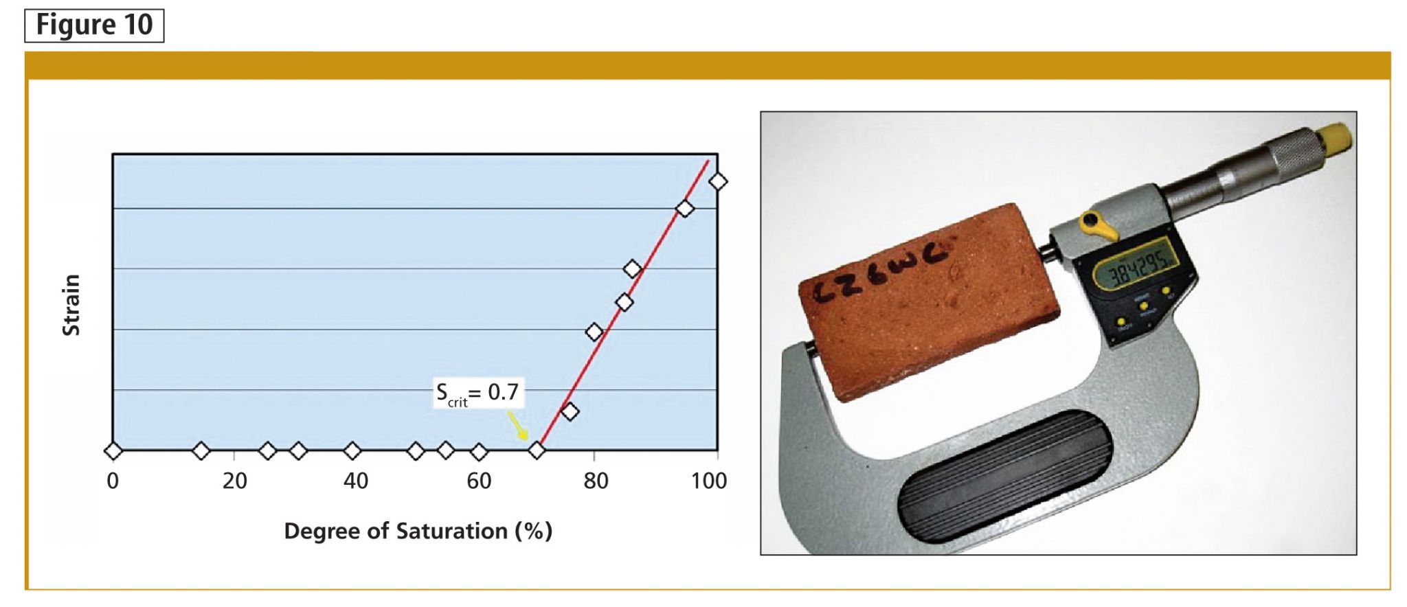
- Frost dilatometry: Thin brick slices at various saturation levels (expressed as a percentage of the vacuum saturation moisture content) are subjected to freeze-thaw cycles. The saturation level at which the sample begins to expand (dilate) under freeze-thaw cycles is termed the ‘critical degree of saturation’ (Scrit), as shown in Figure 10. This value is the material moisture storage threshold/limit, beyond which deterioration is expected. This is a critical material characteristic for assessing the freeze-thaw risk associated with a particular masonry unit.
Comparing load and resistance
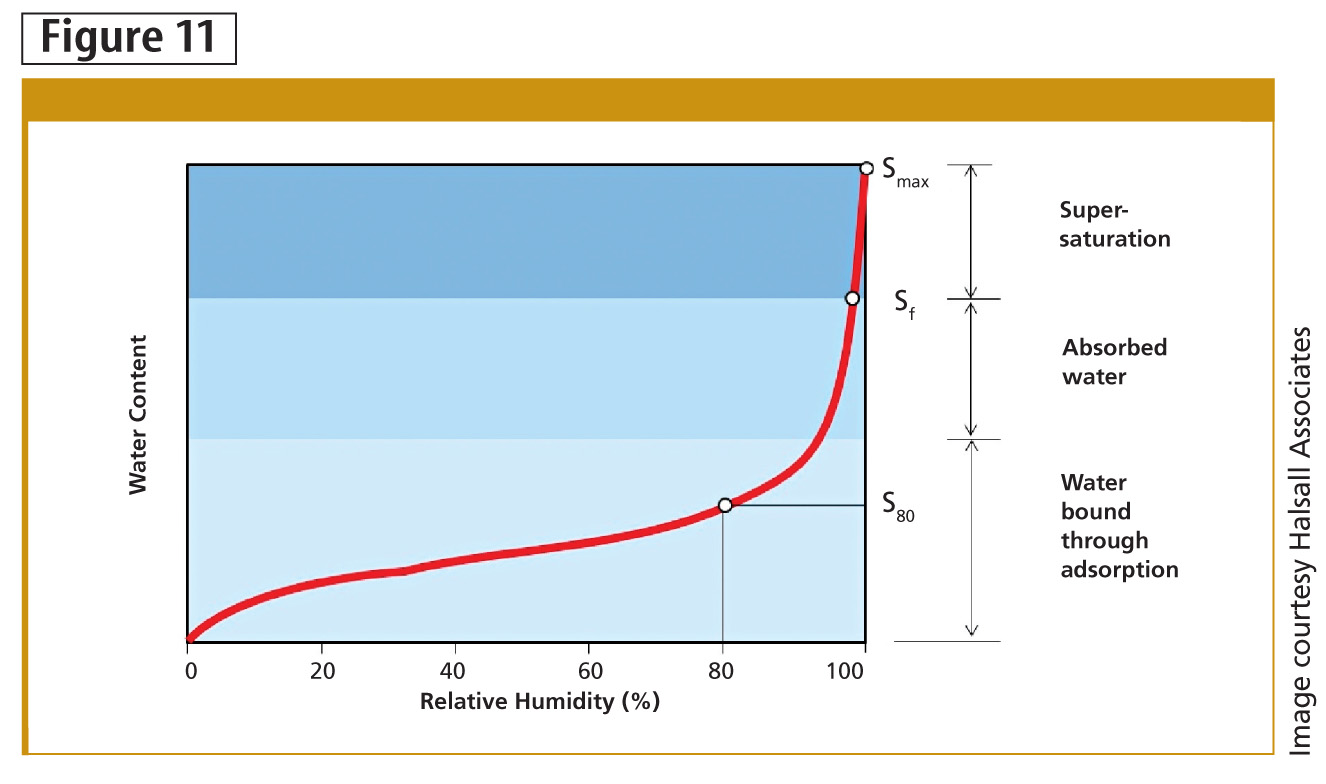
Brick’s moisture storage function could be graphically plotted to indicate the material’s moisture content at various relative humidity values (Figure 11). The Smax, Sf, and Sx (where ‘x’ is the saturation level related to the expected environment within the building wall after insulation, determined from in-wall sensors or WUFI simulation) are plotted over the curve.2 The Scrit value is also plotted and compared to other values. If Scrit is higher than Sf and expected wall conditions, then the brick is likely not going to be exposed to freeze-thaw deterioration issues. If Scrit falls below Sx, then there is risk of freeze-thaw deterioration.
By extension, the wall section must be reviewed for humidity levels that would support corrosion of embedded metal and deterioration of embedded wood. The critical values for wood and metal are published, so additional material testing is typically not required for these materials.
Practical approaches for interior insulation
After identifying the presence of post-insulation deterioration risks in a particular wall, the next steps are to:
- determine the portion of the year when the risks are present;
- assess the impacts on heritage materials, ranging from localized deterioration to significant material loss;
- modify interior/exterior repair details to manage risks (including replacing or protecting any embedded metal or wood components where required); and
- discuss the building owner’s tolerance for conducting ongoing wall maintenance to address expected deterioration.
Designers are considering two main approaches for interior insulation retrofits, both of which entail removal of interior plaster or drywall finishes:
1. Apply a 25 to 50-mm (1 to 2-in.) thick layer of sprayfoam insulation directly on the interior brick. As discussed, applying insulation directly on the brick reduces the masonry’s ability to dry to the interior, and subsequent prolonged wetting may increase risk of future deterioration for embedded metal or wood materials.
2. Leave an air space (‘vent’) between the interior brick and sprayfoam layer, and provide ventilation holes through the masonry to connect the air space to exterior air. This assembly is called a ventilated masonry retrofit (VMR) wall.
The ventilation path is created by fastening one or two layers of drainage mat on the brick. The open-cell woven matrix within the drainage mat acts as the ventilation layer. Drainage mat products incorporating a scrim sheet or filter fabric are more effective, since they reduce the amount of foam that penetrates the woven matrix (otherwise, the air space gets clogged with foam). VMR walls should not be confused with walls incorporating a dynamic buffer zone (DBZ), as the latter includes mechanical systems that actively ventilate/dry the wall assembly. VMR is a passive ventilation approach.
The ventilated air space allows the interior-side of the brick wall to dry, but the exterior vent holes may introduce small amounts of moisture—rainwater or humidity wetting—into the assembly by natural stack effect. Testing a standard insulation retrofit and VMR wall on Toronto’s Barrymore Building—a heritage space recently converted from an industrial project to a commercial one—has shown the latter achieves net drying on the south and east-facing walls, where exposure to wind-driven rain and solar heating are the greatest. Net drying of the wall assembly can reduce the likelihood of bricks reaching critical moisture content levels that would initiate freeze-thaw damage.
Where possible, in-situ testing and data collection of sample VMR and standard retrofit insulation panels is recommended before general installation. Efficacy of either or both approaches could be established; test results can direct which approach is best, based on the direction and environmental exposure of each wall face.
Heritage preserved, future ensured
The existing stock of masonry buildings are ripe for continued use. However, if Canada’s heritage buildings are to be adapted, reused, and enhanced, their thermal performance must be improved to meet tenant comfort demands and owner expectations for energy use.
One step to reduce energy consumption of older masonry buildings is to insulate their exterior walls by applying interior insulation. With careful assessment and testing, designers can detail the insulation retrofit strategy to reduce energy losses without compromising durability.
By balancing new/continued use, preserving façade elements, and achieving reasonable performance standards via insulation retrofits (in addition to adding air seals and updating mechanical equipment), design teams can reduce a building’s energy consumption and increase its occupant comfort while keeping the exterior heritage façade visible to the public.
Notes
1 The authors would like to thank those who contributed to research and project work on this topic. They include Ekaterina Tzekova and Marianne Touchie (PhD candidates at the University of Toronto), Paul Pasqualini of Engineering Link (who collaborated with University of Toronto team on projects and research), and Dr. John Straube, Chris Schumacher, and Randy Van Stratten of the University of Waterloo and Building Science Corporation (ongoing project and research collaboration). Peter Mensinga and Nastassja Pearson, both of Halsall Associates, also contributed project and research work on this topic, including production of graphics for this article.
2 For more information on the Oak Ridge National Laboratory (ORNL)/Fraunhofer IBP program, visit www.ornl.gov/sci/ees/etsd/btric/wufi.
David De Rose, P.Eng., is a project principal and restoration practice leader at Halsall Associates, a consulting engineering company with seven offices across Canada. He specializes in performance analysis, durability assessment, and cladding design for new construction and building renewal. DeRose can be contacted via e-mail at dderose@halsall.com.
Sarah Gray, P.Eng., is a project principal and cladding practice team manager at Halsall Associates in Toronto. She specializes in building envelope rehabilitation for heritage buildings, developing solutions that balance cultural considerations with the demands of modern occupant needs. Gray can be reached at sgray@halsall.com.
Kim D. Pressnail, PhD, is an associate professor of civil engineering, teaching building science within the University of Toronto’s Faculty of Applied Science and Engineering. His research interests include the design and construction of low-energy buildings. He can be contacted at pressna@ecf.utoronto.ca.
Sign up for our weekly newsletter
Construction Canada weekly newsletters give the latest AEC industry news for those who build, design, engineer, specify, renovate or operate in the built environment.
Products & Services


Read the Latest Issue