
By Chuck Mears, AIA
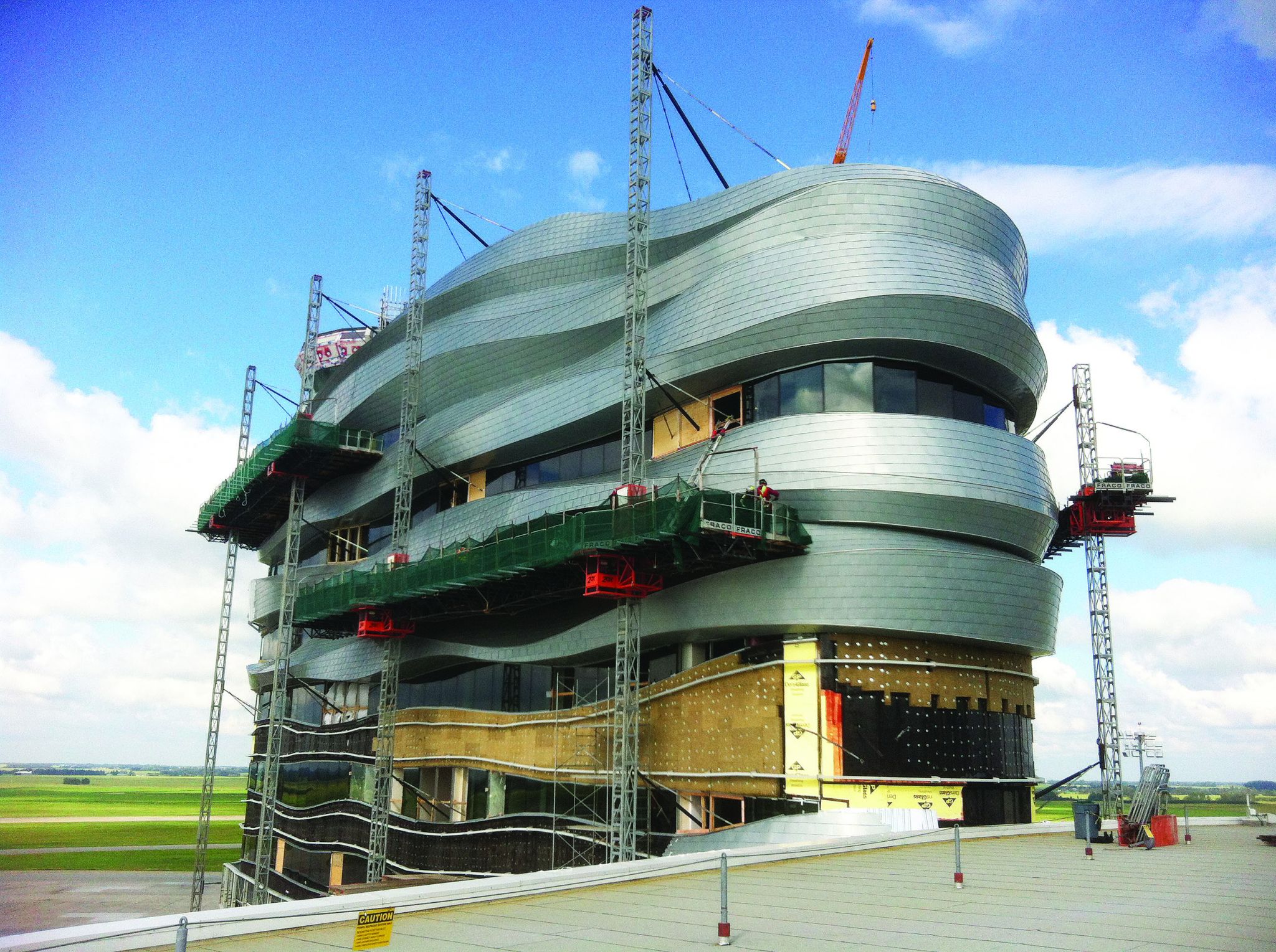
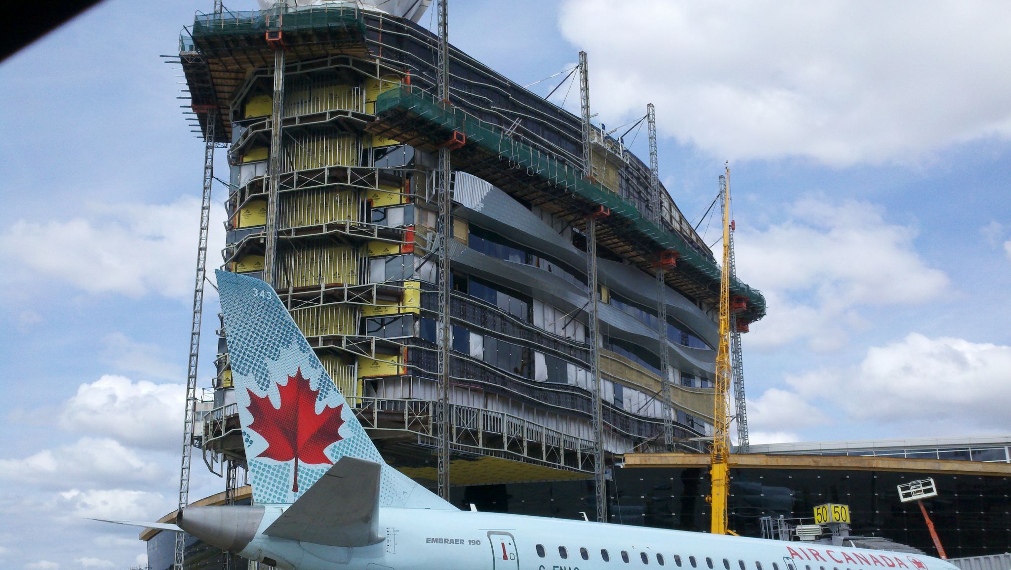
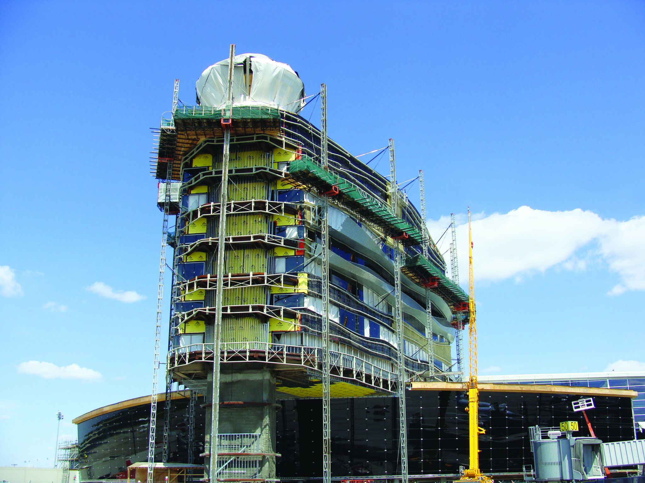
Pilots and passengers landing at Edmonton International Airport will be treated to an architectural achievement not normally granted to utilitarian buildings such as air traffic control towers. The new tower, already an iconic structure on the horizon, features a giant ribbon-like metal ‘wrap’ that twists and turns around the building. The architects, challenged to create a building that would add dramatic impact to the Edmonton arrival and departure experience, created a structure that is not only whimsical and eye-catching, but also cleverly integrates thoughtful sustainability planning. The story of how the giant metal ribbons were engineered to wrap around the building is as compelling as the building itself.
Situated 25 km (15.5 mi) from downtown Edmonton, the airport is surrounded by the windswept prairies that provided the design inspiration. Architect Stephen Boyd of Dialog, the firm that designed the project, says the architectural team took its cue from the tall grasses, which are sculpted by the westward-blowing winds in summer, and are in motion by windborne snowdrifts in winter.
“We felt this imagery expressed a sense of place and its people,” he says.
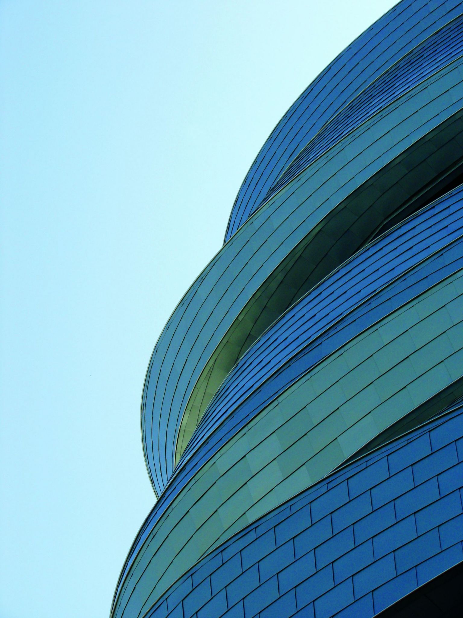
The control tower is situated at the outer edge of a 10,000-m2 (107,640-sf) office building, called the Combined Office Tower (COT). The control tower façade features the metal wrap, which is covered with shingled undulating zinc that has been carefully integrated with windows to maximize daylight and offer shading when needed.
The wrap begins 13 m (43 ft) above the ground and twists upward to its overall height of 45 m (148 ft). Each metal ribbon contains either three or two facets that vary in height, width, thickness, and angle as they trace around the building, depending on the esthetic and shading requirements.
Glazing punctuates the ribbons to provide panoramic views of the surrounding prairie landscape. Designed to meet Silver under Canada Green Building Council’s (CaGBC’s) Leadership in Energy and Environmental Design (LEED) program, the building is situated to maximize natural solar advantages. An optimal east/west solar site orientation minimizes solar gain from the western exposure. The ribbons were also carefully designed to control solar heat gain and harvest natural light. They were also sculpted to meet rigorous viewing requirements set forth by Nav Canada for air traffic controllers watching the tarmac, runways, and skies.
Creating curves
The curves in the airport tower have a long pedigree. Ancient Greeks and Romans were the first to explore the beauty of curves and arches in architecture, with their Gothic and Romanesque forms that have graced churches and palaces through the centuries. Until very recently, however, devising perfectly formed curves was more of an art than a science. Most curved surfaces were created strictly in the field, sometimes with irregular results. The tools and techniques to construct geometrically accurate curves did not exist. Today, modern technology has helped transition the creation of curves to a scientific, duplicable process ensuring curved walls, roofs, and other surfaces can be fabricated with geometric precision and consistency.
Prior to computer-aided design (CAD) and fabrication, wood framing was a common method for creating curves. In this case, notching and other scoring techniques were employed in an attempt to shape the wood framing members. Since the notching inherently weakens the member’s structural integrity, gussets or other plates were added to bolster the framing piece. This allowed the member to hold the weight of the finish materials being supported or, in some cases, the entire assembly was suspended from another structural system above. The finish material was often some form of interior plaster over a freeform lathe installation. In ornate settings, the still-wet plaster was intricately painted to create frescos. While beautiful, these ornate frescos fulfilled another purpose—hiding irregularities in the surfaces.
More recently, gypsum board—scored and often soaked in water to make it pliable—replaced the wet plaster. Making a sheet material warp and bend is also more art than science, particularly when mudding the panel intersections in an attempt to smooth out the finished product. Eyeballing and craftsmanship became necessary tools on the jobsite.
When contractors began to explore the use of steel to create curves, studs and/or track were ‘snipped and strapped’ to contort the framing member into its required profile. Unfortunately, the bent members were as consistent as the craftsmanship of the snip-wielding worker. The spacing of the snips and the angle at each bend became infinitely variable. With every member modified differently, it was very difficult for contractors to provide accurate bids for the work.
As the process of controlling the bends on steel framing members evolved, the ‘stretch forming’ approach was introduced. This involves stretching and bending members around a specific-sized, custom-built form using large-capacity, hydraulic stretching equipment. The process, while effective, is unfortunately not very flexible due to the individual custom forms required to be built for each radius in the design; it also can drive up costs.
To make the exterior stretch-formed members affordable, designers were required to settle on a limited number of radii (to limit the number of custom forms to be built) and adjust the design to use only existing forms. The limitations of stretch forming and its inherent compromise of design intent was the impetus for further innovation, such as proprietary tools to work with pre-curved members that are site-bent and shop-fabricated using cold-formed steel.
This approach uses calibrated bends in the web and/or flange of standard steel tracks and steel studs to precisely curve members to match the design intent. Pre-built forms no longer limited the interior framing used, and therefore a much broader range of curve options become available. Most surface framing systems, including heavier structural stud and track elements, can now be efficiently produced with larger pneumatic and hydraulic benders. The ability to curve track flanges independently of the track web adds the capability for compound bending configurations. This removed the final limitations on designers for all kinds of compound-curved surfaces.
The next step in automation and process refinement was integrating 3-D modelling software with the fabrication process. This interface yielded a method of transferring data extracted directly from a computer model, into an automated manufacturing process.
‘Air-side’ challenges foster collaboration
For the Edmonton project, construction was done ‘air-side’ at the airport, which meant some unusual challenges for the building envelope contractor, Thermal Systems KWC Ltd. The project, which was complicated enough given the asymmetrical ribbon construction, also had to be built close to active gates.
“Having a construction site that was air-side with airplanes coming and going on regular schedules was a challenge in itself,” says the firm’s architectural cladding and roofing manager, Trish Griep.
Confronted with such unusual conditions, Thermal Systems knew they needed a high level of constructability and control to engineer and install the ribbons. The result was a partnership between Thermal Systems, Gehry Technologies (GT) in New York City, and the curved, cold-formed steel framing provider.
The owners and construction manager selected GT to join the construction team to execute the master construction model for the project. Facing extremely tight deadlines, which were suddenly accelerated mid-project, Thermal Systems was able to use GT’s extraordinary ability to process large volumes of complex data and the framing company’s ability to fabricate to exacting specifications and ease the onsite assembly with ‘erector-set’ simplicity.
Thermal Systems had originally explored using curved pipe to control the geometry of the ribbons and to provide an attachment point for the steel decking and zinc panels, which make up the ribbon surface. But creative thinking by the three companies provided another solution that worked extremely well and helped produce the building’s graceful curves. The group found a way to provide an extremely smooth surface, manage the complicated air-side working conditions, and ultimately better reflect the dramatic statement created by the twisting ribbons.
Parametric modelling to define geometry
When GT came into the project, it decided to use site surveys instead of the original construction documents to better define the exact location of each truss that would support the metal ribbon.
“With these types of projects, there are subtle differences in form, so geometry makes all the difference—our job was to find a way to improve the constructability of the project,” said the firm’s senior project consultant Jason Sidelko. “Coming in mid-project, we had to find a system that would work with the existing steel and glazing systems that were already in play.”
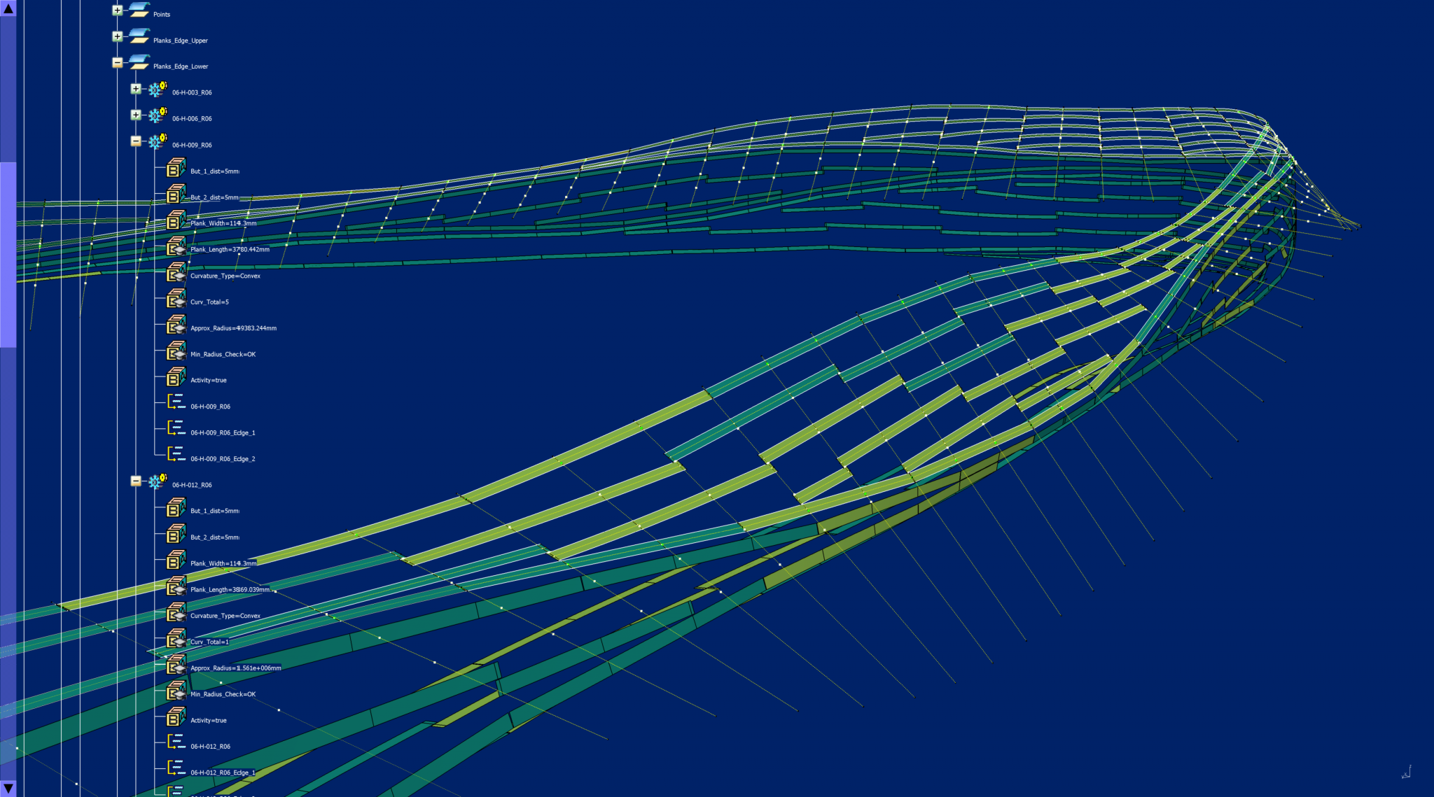
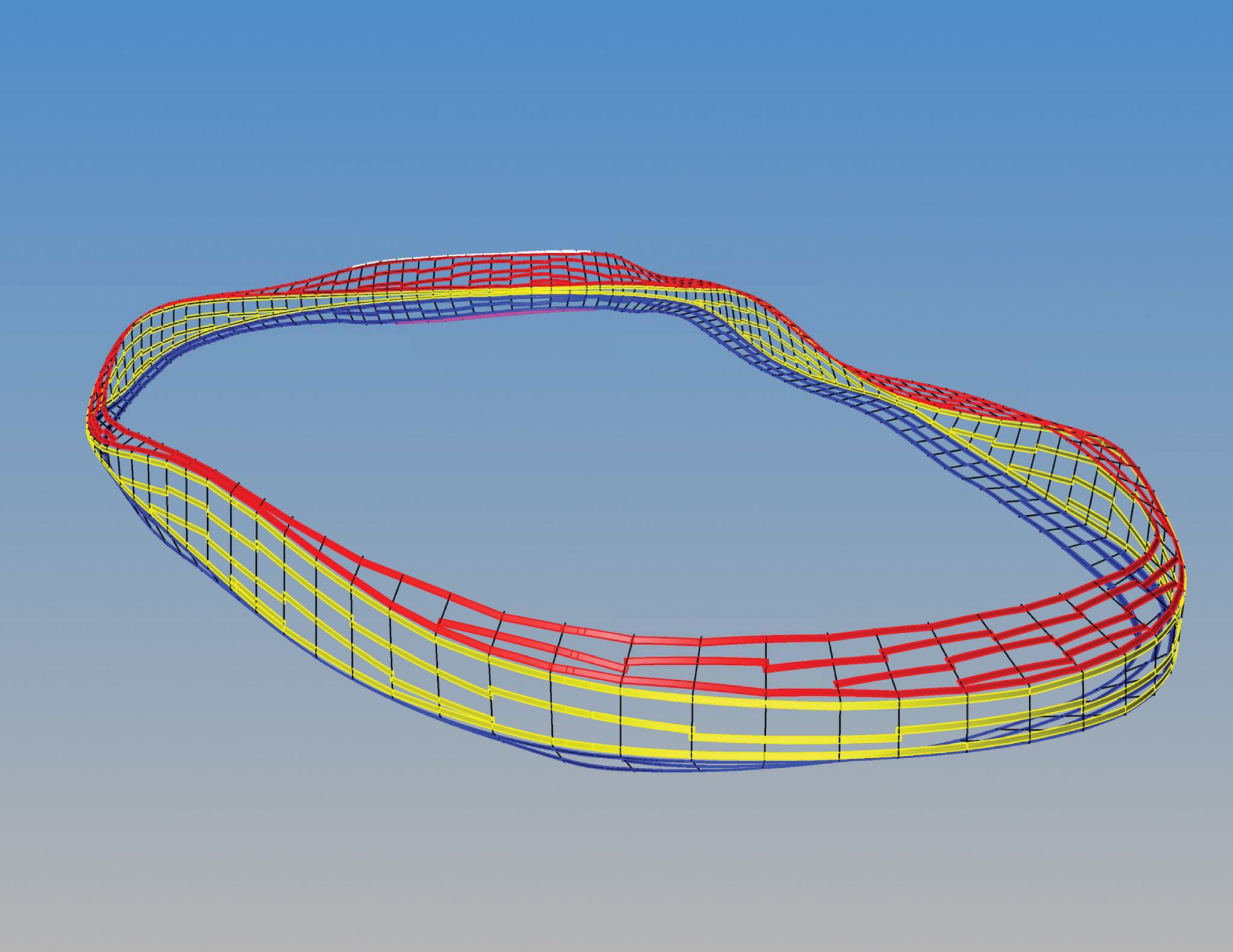
GT is known for its work in parametric modelling, which allows the data entered into a building information model (BIM) to be altered, and the effects of that change to be understood immediately. ‘Known’ data (or rules) are coded into the BIM model, and then propagated to study the effects of the known rules, and what happens when those rules are changed (even very slightly). The system not only accurately predicts the design of the building, but also highlights where potential problems or clashes exist.
“We simply put all the rules into the digital environment, but we rely on our team partners to supply us with the data and expertise to create those rules—it is truly collaboration,” explains Sidelko.
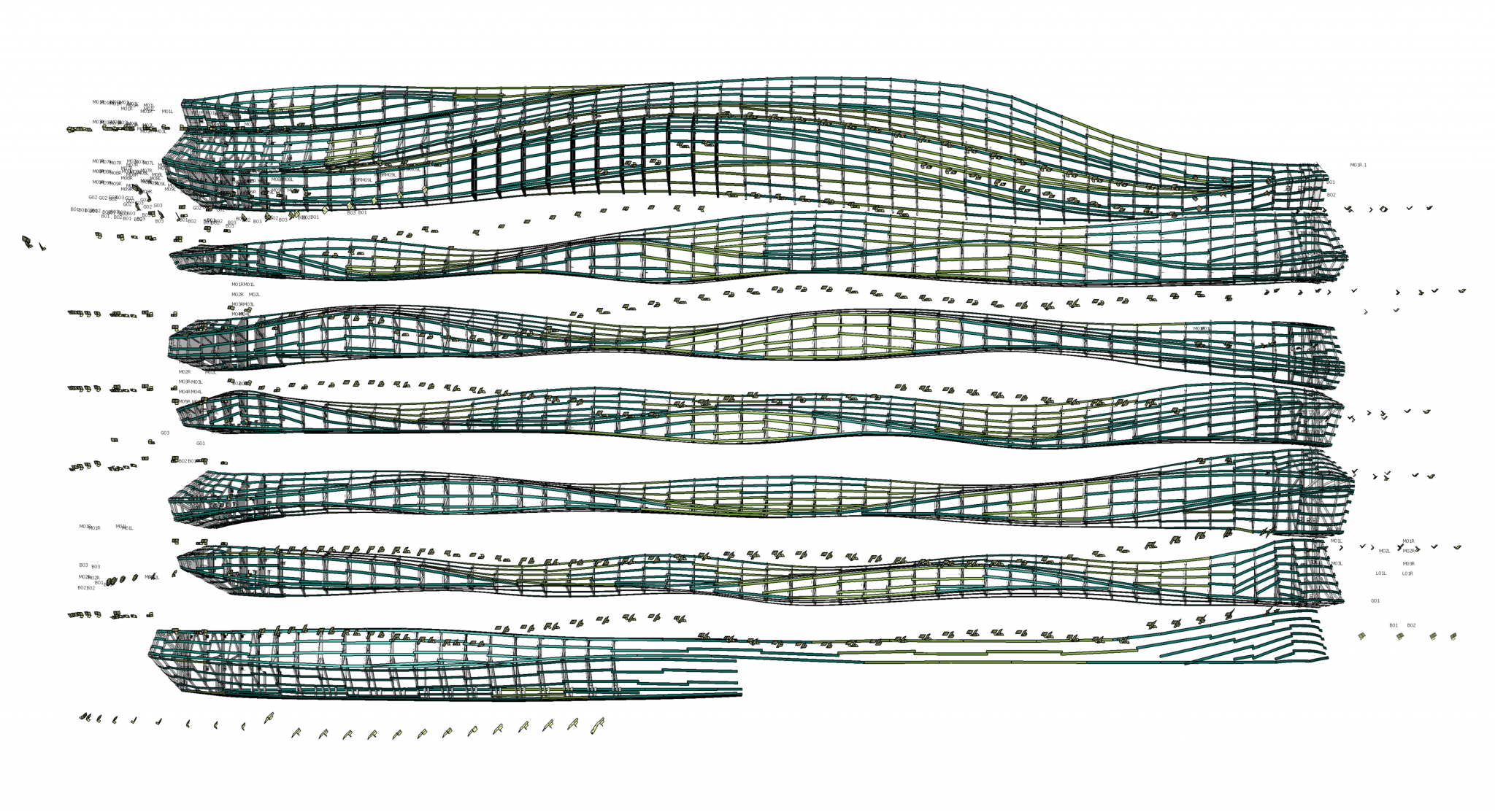
Using this data, GT was able to model the curved surfaces and underlying trusses for the project with exceptional accuracy and detail.
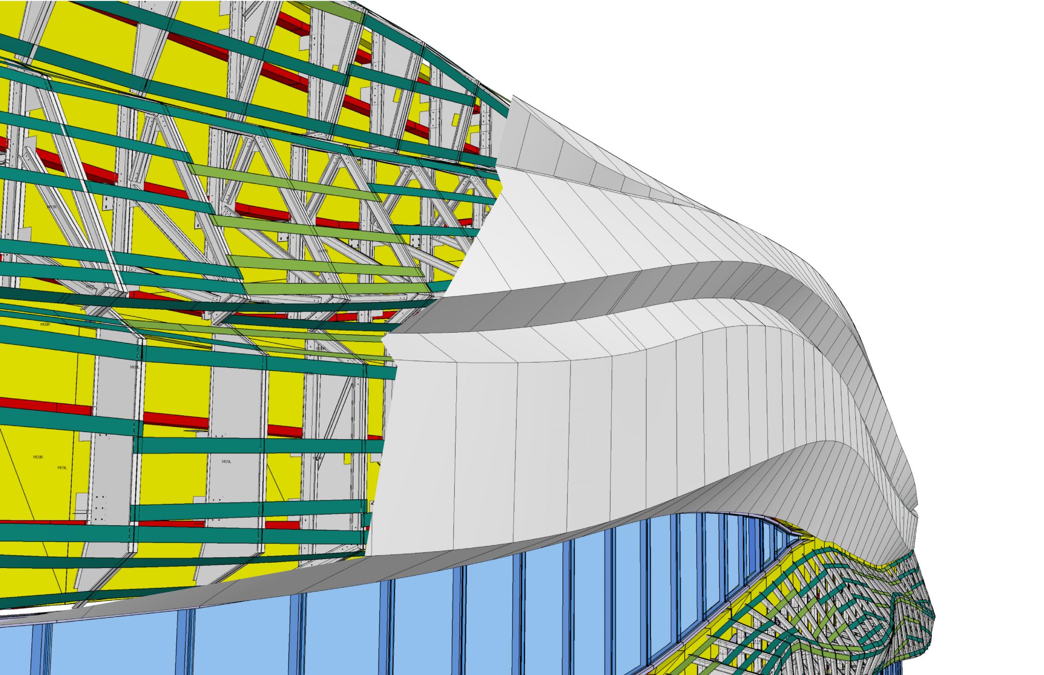
Accuracy defined by new hat channel concept
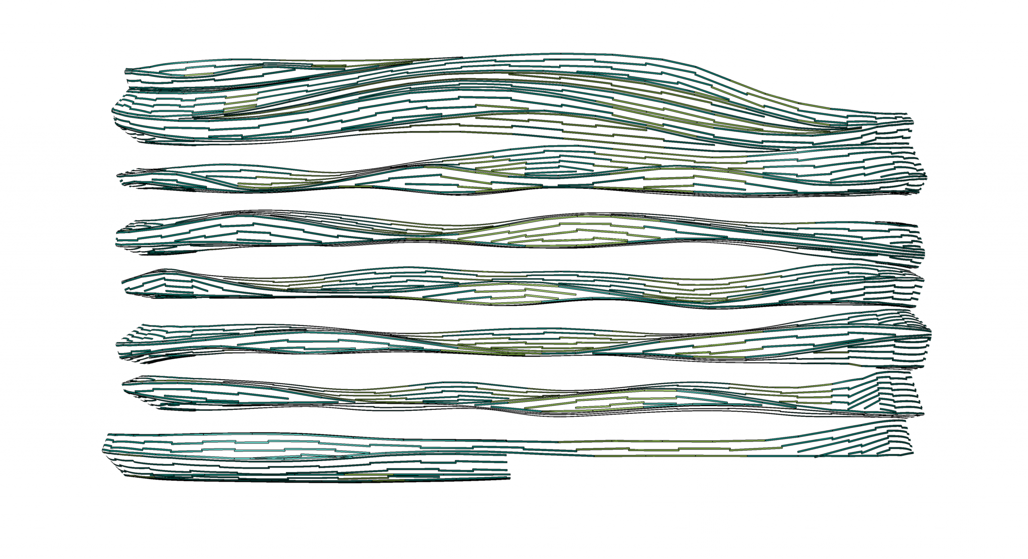
Necessity is often the mother of invention, and it became evident an entirely new solution could best achieve the twists and turns of the metal structure. The team developed a simple solution—a method for curving hat channel—that provided a smooth surface for the finishing material and more importantly, served as a way to ensure accurate and easy installation. The hat channel was attached to the trusses and served as the surface to attach the decking and zinc finish. Since the channel could be fabricated to a highly exacting curvature, it arrived on the jobsite perfectly aligned to the trusses. As the metal ribbon twisted and turned around the building, the underlying hat channel had to be curved to meet each unique bend. The degree of accuracy was so high the hat channels were used to help place the location of all the trusses.
Due to the project’s magnitude, the concept of parallel design was used as the team worked its way up the building. As GT fed the data to the framing company, the latter used its propriety computer numeric bending (CNB) machines to fabricate each piece of hat channel. Fabrication time, by necessity, was often a mere seven days from receiving the data to shipping it out the door.
However, those seven-day windows of time included another critical step—coding and organizing the channel in such a way it could be quickly staged and assembled onsite. To accomplish this, Thermal Systems and the framing company developed a nomenclature to help identify material at the jobsite, which included a special labelling system to match up the hat channel with the trusses.
Prior to shipment, all material was meticulously sequenced and packaged. On arrival, Thermal Systems needed only to match up the numbers and colours. Another challenge was the height of the structure (the top level is 12 storeys off the ground). Specialty mast-climbing platforms were installed to provide Thermal Systems access to the building exterior, but the staging area onsite was extremely tight as it was air-side. Using feedback from the Thermal Systems installation team, the framing company took this into consideration and shipped everything in scaffolding-sized packaging to help ease the installation.
The new hat channel solution brought multiple benefits to the project.
“The updated materials used were significantly more efficient and allowed for a faster and less-complicated installation with a higher quality result due to the special labelling of each part and the sophisticated delivery system,” said Thermal Systems’ Tyler Weisgerber.
Conclusion
When the new tower opens (scheduled for January 2013), it will stand as an icon—a significant building for travellers visiting the Edmonton International Airport. The free-flowing twists and turns of the building can be enjoyed from some areas of the terminal, and by those approaching the airport by car. As Canada’s fastest-growing airport, the tower is a distinctive design statement that will be appreciated by the six million people who use the facility each year.
 Chuck Mears, AIA, is the CEO and chief design officer for Minneapolis-based Radius Track. Through his expertise on cold-form steel structures, architects such as Frank Gehry, Moshe Safdie, and Douglas Cardinal have been able to push through the design barriers of creating curved surfaces. Mears’ pioneering work in building information modelling (BIM) technology and fabrication allows his team to create steel structural systems to support any architectural form imaginable. He can be contacted via e-mail at chuck@radiustrack.com.


