
By Patrice R. Tardif, LEED AP
The University of British Columbia Okanagan (UBCO) campus is located in the province’s southern interior, on the outskirts of Kelowna. The school strives to provide an active and vibrant community life for resident students—a considerable challenge given the distance from the city centre and the doubling of the student population in just 15 years.1
While some of the university’s facilities, including those for competitive athletics, have accommodated the growth in demand, recreational and fitness facilities have not. The Athletics and Recreation Department converted an existing storage area adjacent to the gym into a weight room and cardio workout area, but this was only a temporary fix for what was clearly an ongoing problem. A permanent solution became possible only when the university received a substantial private donation toward the construction of a new dedicated fitness facility.
The donor stipulated two conditions—the new facility should demonstrate innovative use of local wood products and, given the donor’s ownership of an aircraft maintenance company, have an aviation theme. The university chose to implement this project through a design/build competition, which was ultimately won by Kindred Construction and McFarland Marceau Architects in partnership with Equilibrium Consulting as structural engineers.2
Design concept and building program
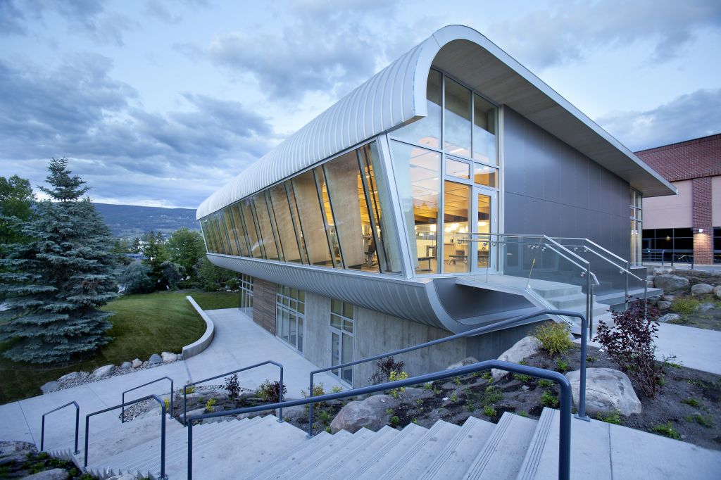
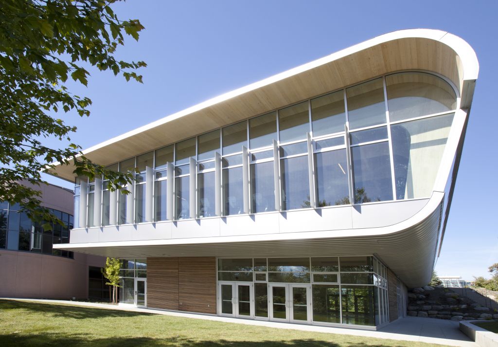
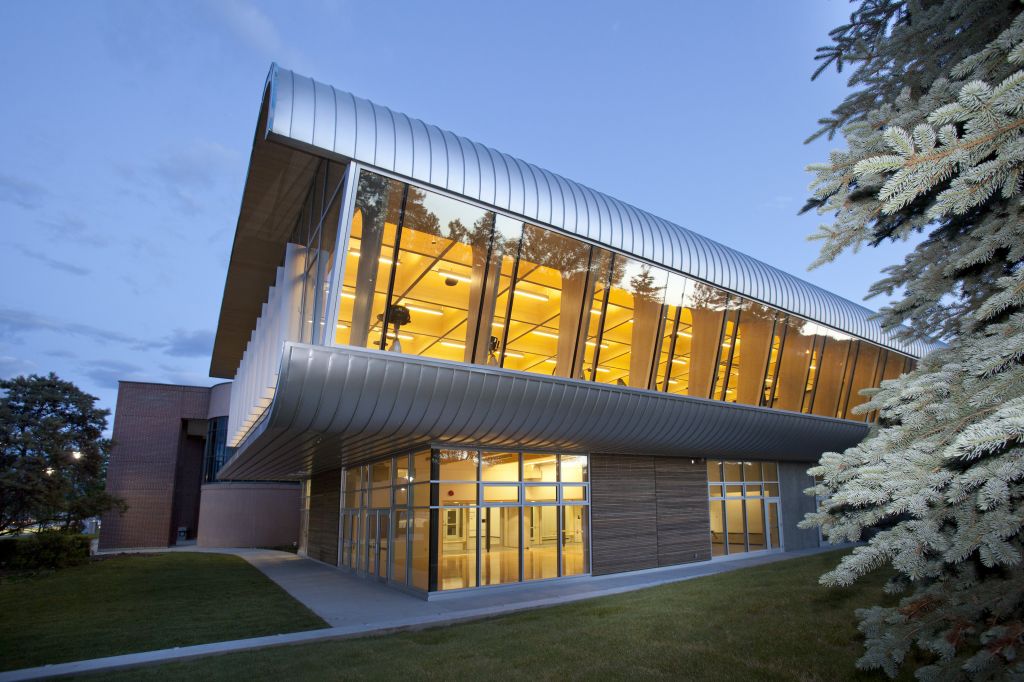
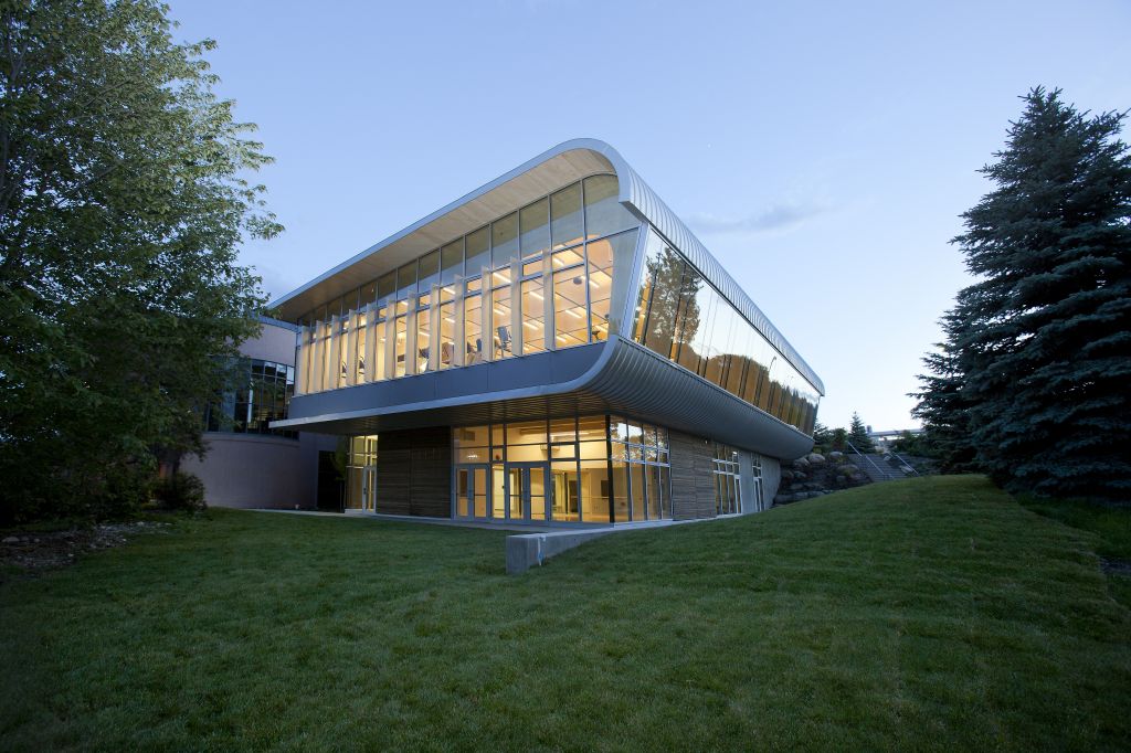
The form and materials of the new Fitness and Wellness Centre (FWC) are in deliberate contrast to the predominant dark masonry cladding and simpler geometries of other campus buildings. The pavilion, or the Hangar as it has come to be known, is located to the north of the existing gymnasium, and attached to it with a 7.5- m (24 3/5-ft) long, two-storey glazed link.
The new building is set at an angle to preserve views down University Walk, the main pedestrian axis on the campus. Glazed façades to the north and east connect the interior spaces to views of the Okanagan landscape beyond.
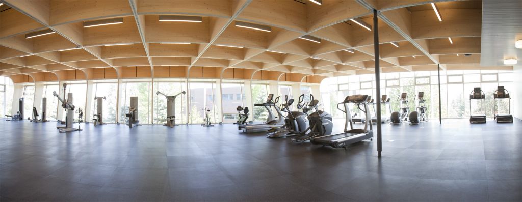
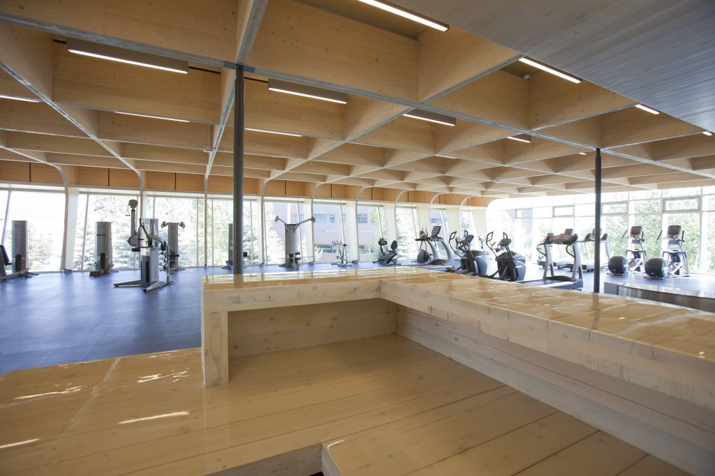
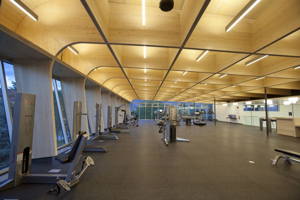
The sloping roof of the FWC takes the form of an airplane wing, its curved leading edge turning down to meet the inclined glass façade of the upper storey. Through this glass is the exposed wood roof structure with a honeycomb configuration inspired by the wing of a World War II Mosquito bomber. The upper-storey cantilevers beyond the cedar-clad lower storey, accentuating the structure’s lightness and agility. The result is a symbolic gesture in keeping both with the aviation theme and the building’s athletic purpose.
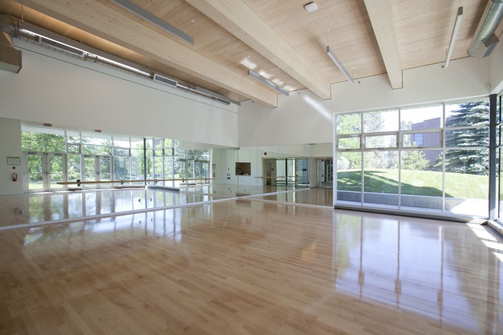
The interior consists of a cardio exercise area, a weights and strength training area, and various studio spaces for yoga, combat sports, stationary bikes, Pilates, and dancing. Since access to the two main levels of the FWC is via the glazed link, the new facility did not need internal stairs or an elevator.
Choosing CLT
The teams at McFarland Marceau and Equilibrium Consulting had previously designed several buildings using lightweight cross-laminated timber (CLT) and, with one of Canada’s two manufacturing plants in nearby Penticton, their thoughts immediately turned again to this relatively new material.3
CLT panels have typically been used as mass wood wall and deck systems, but the material offered the promise of an entirely new building system, explains Craig Duffield, lead architect with McFarland Marceau.
“This project provided an opportunity to put the material through its paces,” he says. “CLT is not inherently strong as a beam, but when considered like those components in nature that are not strong on their own but achieve strength in assembly—like the cellular structure of wood—interesting possibilities emerge.”
CLT panels are fabricated by stacking alternating layers or plies of structural-grade lumber at 90 degrees to each other in odd-number layups, with a minimum of three plies. These are subsequently either glued together or mechanically fixed to form large panels. Due to the nature of the manufacturing process, CLTs have improved dimensional stability with increased strength and stiffness in both directions, giving the panels a two-way action much like that found with two-way concrete slabs, only with less weight. CLT panels are available in finish and industrial grades.
The material’s use also allowed the design to speak to aviation theme, says J. Eric Karsh, a structural engineer with Equilibrium and a past contributor to Construction Canada.4
“The idea of cutting airfoil-like shapes out of CLT panels to create a deep, but delicate-looking, grid structure came out of my childhood passion for building balsa wood model airplanes,” he says. “CLT panels lend themselves well to this approach because of the cross-lamination, which gives the panels strength in both in-plane directions.”
Code considerations
The FWC falls under the assembly occupancy, Group A, Division 2, according to the British Columbia Building Code (BCBC). As such, it was permitted to be of combustible construction if fully sprinklered and protected by a two-hour fire separation on the side facing the gymnasium. In fact, the design team chose to create a one-hour fire separation at either end of the link, using concrete masonry at the FWC end, and two layers of 16-mm (3/5-in.) gypsum wallboard at the gymnasium end.
The suspended floor was required to be a one-hour fire separation, but there was no fire resistance or heavy timber requirement for the roof structure.
Construction
The two-storey FWC pavilion uses a hybrid construction system—the primary material being wood, employed in combination with steel and concrete. At the ground floor, concrete shear walls (one that rises the full two-storey height), a few strategically placed hollow structural section (HSS) steel columns, and two CLT box-rooms form the structure’s basic elements.
It helps to think of the building in two sections to either side of the single interior column gridline. This column line acts as a transfer zone for the differences in structural treatment to the north and south. Glued-laminated timber (glulam) beams for the upper level floor system define the main grid lines of the roof system above. They cantilever beyond the wall in the north section of the building and support the CLT roof frames.
A wood-concrete composite floor system is supported on the glulam structure to the north of the transfer beam and spans freely between the transfer beam and the back (south) wall.
The roof consists of slender 99-mm (3 9/10-in.) thick CLT ribs at 2.3-m (90-in.) centres that, to the north of the transfer beam, connect to tapering CLT columns to create a series of rigid moment frames. The beams increase in depth from 940 mm (37 in.) at the transfer beam, to approximately 1500 mm (60 in.) at the column connection. The beam-to-column connection is a 45- degree split joint. The CLT column tapers to 600 mm (in.) at its base where it connects to the projecting glulam floor beam. The CLT beams are braced laterally with CLT stiffeners also at 2.3-m centres.
The roof deck is also CLT panels—cut into narrow strips to form the curves at the north end. Nearly all CLT used in the Hangar is three-ply, except for the transfer beam (five-ply) and the roof panels for the link (seven-ply).
Connections
Wood components were joined using various high-efficiency connection systems. One type of proprietary shear connector used consisted of perforated steel plates or mesh simultaneously imbedded in adjacent materials to create a composite action between the two.
To create the composite action in the wood/concrete floor, half the connector’s mesh was inserted into precut grooves in the CLT floor panels and glued in place with a proprietary epoxy-based adhesive system. Concrete was poured on top, creating a mechanical shear connection when the concrete cured.
Another type of proprietary connectors used on the project was particularly suited for creating rigid moment frames in wood structures. A series of heavy-gauge perforated metal plates were installed in factory-cut grooves of the elements to be joined. The rigid connection was achieved by injecting an epoxy into the connection onsite through pre-drilled holes. The size, number, and design of plates varied with connection geometry and loading.
In the FWC, there are two types of moment connections:
- where the CLT roof beams meet the tapering CLT columns on the north façade; and
- where the base of these columns attaches to the glulam floor beams.
The connectors in question can also be used to attach the end of one element onto the broad side of another element, as was the case in connecting the CLT bracing elements between the CLT roof beams. A metal plate was mounted at 2.3-m centres along the face of the beams and HSK mesh factory welded perpendicular to it. The bracing elements, with factory-cut grooves in their end surfaces, were mated to the beams onsite and epoxy injected to complete the joint.
A third type of proprietary connectors were high-strength aluminum dovetail products that were precision-installed in the fabrication shop. Once onsite, elements were simply slipped one into the other, creating an invisible, form-fitting connection. In the roof of the FWC, the standard beam construction portion uses these connectors, as do the bridging elements to north and south of the transfer beam.
Fabricating and modelling
Fabrication of CLT and glulam components and connection detailing took place off site at a plant in Penticton. Early involvement of the fabricator in the design process enabled both materials and the manufacturing process to be optimized.
A 3D modelling program—CadWorks—was essential in determining the beam/column cut-outs in the panels to keep waste to a minimum. Careful arrangement of patterns (as for the balsa wood model airplanes mentioned by Karsh) meant multiple pieces could be computer numeric control (CNC)-cut from each 3 x 12-m (9 4/5 x 39-ft) CLT panel. All the wood components left the factory ready for installation.
Onsite construction began last April, and the wood package deliveries had to be co-ordinated as the work progressed. All concrete and structural steel work had to be completed before the first CLT packages started to arrive that summer.
The first shipments included the CLT panels for the ground floor, the glulam transfer beams, and the regular glulam beams that would support the composite floor. Subsequent shipments included CLT components for the upper floor and catwalk. The concrete topping for the floor was poured in October, followed by the installation of four HSS columns and the glulam transfer beam. Thus, the stage was set for the installation of the roof structure.
Responsible for erecting the wood components, John Boys of Nicola Logworks had already determined assembling the moment frames on the ground then raising them into place would create too many stresses. He therefore developed a cradling system to facilitate the erection. Two rib beams were installed at a time, cradled in place at the north wall to support that end, and the column portions were brought in and pivoted into position. Once the bridging elements were dropped in, the moment joints were epoxied.
Epoxying the moment joints on site proved to be challenging. The volume of epoxy for the joint geometry was calculated and hydrostatic pressures that can build with the injection of large volumes were factored in. Vent holes were needed to keep air from getting trapped during injection, but leaks had to be prevented to ensure the proper volume remained in the joint. Each moment connection took about two hours to complete.
Once the roof structure was in place, the CLT panels for the roof deck arrived and were installed. The five-week installation period for the wood components was shorter than anticipated, but waterproofing the roof was a challenge given the more than 100 penetrations for electrical boxes and conduit.
Conclusion
As a new construction system to North American designers, the potential of CLT has only just begun to be explored by architects and engineers. Known in Europe for its strength and durability, the University of British Columbia Okanagan Fitness and Wellness Centre demonstrates that CLT can also offer grace and beauty.
Mary Tracey, executive director of Wood WORKS! BC industry group, described the result as “remarkable” and “innovative.”
“The exposed wood structure, natural light and views make a compelling combination, attracting fitness enthusiasts to the facility even on days when motivation is low,” she says. “As designers embark further on the learning curve for this new building system, we can already see that the whole is greater than the sum of the parts.”
Notes
1 For more on the university campus’ recent design/construction projects, see the article, “UBCO Labs Lead the Way” by Michael McDonald, Honor Morris, Guy Taylor from the October 2012 issue of Construction Canada. (back to top)
2 This article was condensed by Jim Taggart, Dipl. Arch. (Hons), M.A., FRAIC. His previous articles for Construction Canada include “Why Wood Works: Designing the Richmond Olympic Oval” in the November 2009 issue and “Mid-rise Makeovers: B.C. Code Changes Encourage Building with Wood” in September 2012. (back to top)
3 Additional information on CLT can be found in “The Advent of Cross-laminated Timber,” by David Moses, PhD, P.Eng., PE, LEED AP, and Sylvain Gagnon, Ing., in the March 2011 issue of Construction Canada. (back to top)
4 For other Construction Canada articles by Karsh, see “Building the Earth Sciences Building at the University of British Columbia” in the April 2013 issue, and “The Sky’s the Limit: Designing Airports with Wood” in September 2012. (back to top)
 Patrice R. Tardif, LEED AP, is president and CEO of Patrice Tardif Consulting and a past-president of the board for the Forest Products Society. She is a consultant and researcher experienced in the management of technical, regulatory, environmental, and market issues of concern to the North American wood products industry, with an expertise in sustainable development and the green building portfolio. Previously, Tardif was technical director for the Composite Panel Association and market development specialist and quality auditor for APA−The Engineered Wood Association. She can be reached via e-mail at ptardif@bell.net.


