Five common mistakes made in the façade industry
By Jeff Ker

Looking at the façade industry today and for the future, there is a progression toward lightweight/low-mass solutions. This is in response to the demand for lowering the amount of embodied energy in the construction industry in an effort to address environmental impact of buildings. Lowering the weight suspended from the building superstructure will also save costs. Over the last decade, more of these solutions are being employed with success, both in function and form. While largely developed in Europe, these solutions have either made the transition to the North American environment seamlessly, or with small changes in the assembly design. These contemporary and future-friendly façade solutions of both skin and substructure have best practices to follow, and through this, promise good performance with long lifespans (future-friendly designs refer to lower embodied energy solutions to minimize carbon footprint and provide superior thermal performance to address the more demanding building code requirements). This article addresses the five most common mistakes made, as it applies to future-friendly façades.
Mistake #1: Inadequate ventilation
All façade solutions benefit from good ventilation. Yet, the industry continually witnesses systems going up without it. Ventilation has two principle benefits. It helps dry the envelope when there is moisture intrusion, a significant factor affecting the durability of a building envelope. Building moisture can cause mould, corrosion, decay, freeze/thaw damage, and other moisture-related deterioration.

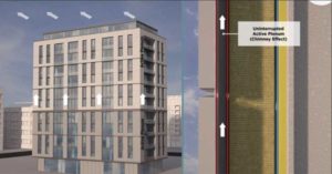
Early research in Norway in the 1960s revealed that rainscreen systems are quite effective in managing moisture intrusion. Manufacturers of various systems might claim to be a ‘rainscreen,’ as there are many definitions for it. The one system definition consistently delivering high performance is that of DIN standard 18516, Cladding for external walls, ventilated at rear – Part 1: Requirements, principles of testing. This particular design is unique as it prescribes a vertical active and uninterrupted cavity or ‘stack effect’. The continual ventilation cavity works with the natural flow of air. Hot air rises, so in the warm months, air in the cavity flows. The cavity is typically 25 mm (1 in.) deep with an opening at the top and bottom. As the air flows through the cavity upward through single or multiple storeys, a vacuum is created. The vacuum is a natural and highly beneficial phenomenon largely due to the stack effect, which conveniently pulls and draws moisture, exhausting it as vapour from the assembly. This method of ventilation is superior to an interrupted system relying on an unnatural horizontal flow.
There is also another benefit of this vertical active cavity—the ability to exhaust heat energy. In summer, when solar heat gain is bearing down on the façade, energy will naturally radiate inward. In an effort to keep heat away from the building’s core and raise the interior temperature, it will be exhausted upward, out of the façade assembly, and away from the building. The 25-mm active ventilation cavity is, in fact, a microclimate. This benefits insulated and non-insulated envelopes, but for the purpose of this article, the envelope will have some form of continuous outboard insulation. This microclimate is neither the temperature outboard of the cladding nor the temperature within the insulation plane, or the interior of the building.

The microclimate assists in stabilizing temperature fluctuations. It reduces the façade skin thermal stress and also limits solar heat gain from taxing the interior climate.
A part of the assembly involves a weather membrane directly in front of the insulation, but behind the 25-mm cavity. This membrane performs the function of a secondary drainage plane. When precipitation enters through the open joint system often found in façades, the weather membrane will prevent the liquid moisture from entering the insulation plane. These membranes can withstand a head of water. These membranes should ideally be ultraviolet (UV) stable and must be placed directly against the insulation to prevent buffeting and counteract some of the ill-effects of wind load. If ambient moisture through condensation finds its way into the protected insulation plane, it can be drawn outward through the membrane as vapour through the vacuum created by the upward movement of air in the 25-mm cavity. This whole prescription and process helps address and respect the Ontario Building Code (OBC) division B Part 5 Environmental Separation and Part 9 of Housing and Small Buildings (particularly A-9.27.2).
To summarize, ventilation through the 25-mm active cavity encourages the envelope to dry. Lastly, there is a thermal benefit from the cavity and microclimate. Engineering firm Morrison Hershfield found through finite analysis exploring a proprietary thermal clip in 2012, the 25-mm cavity offered as much as 0.7 R-value.


